 Facebook
 Google
 GitHub
 Linkedin
A recent addition to my standard breadboard setup in two small DC voltmeters. I have found it beneficial to have meters committed to the breadboard to give instant feedback on the circuit I'm working on.
Other items on my breadboard ...
Battery powered, + and - 15 V from AA battery packs.
+5 V regulator, LM78L05 with a 2N4403 bypass transistor, so I have about 250 mA available.
Two adjustable voltage sources, + to - 12 V, LM358 and trimpots, with the option of adding buffer transistors on the output.
A simple inverter circuit, LF356 running from + and - 15 V to invert a negative voltage to positive so the meter can read it. The meters do not read negative voltages. What do you want for $5.00 meters?
One 2.5" x 6.5" breadboard mounted to a replaceable basswood plate.
All this in a 9" x 12" wooden box which gives me ample top space for attachments and projects and storage space inside for batteries and other breadboards.
I have a shoebox of doodads and attachments (signal generators, digital and analog add-on circuits built up over the years. Battery powered 60 Hz sine wave source, signal generators ...).
I prefer plain wire jumpers over the high quality jumper wires with connectors. The plain wires just take up less space on the board.
In retrospect I might advise to spend a little more and get meters that read positive and negative voltages, and more current on the +5 V supply. Maybe a separate voltage source for that. Maybe two 18650 batteries to drive that. But that would just be using what I have on hand, no other reasons.
AC wall wart power packs? I have them available. Literally, I have hundreds. I can throw together most any voltage or current I need for a project in short order.
(edited to add...)
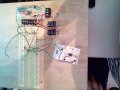
In the picture attached the small breadboard at the top is power stuff (two variable supplies and +5 Volts). the TO-39 case is the LF356 inverter if I want to measure negative voltages on one of the two meters.
The small breadboard on the right is a current project. "760" is the design number so I can reference the schematic if I need to.
I use the main breadboard for early development of circuits. Once I get a circuit close to working I put it on a small breadboard with dedicated parts and wires. Seldom does a circuit get developed to be committed to a PC Board and/or a box.
Other items on my breadboard ...
Battery powered, + and - 15 V from AA battery packs.
+5 V regulator, LM78L05 with a 2N4403 bypass transistor, so I have about 250 mA available.
Two adjustable voltage sources, + to - 12 V, LM358 and trimpots, with the option of adding buffer transistors on the output.
A simple inverter circuit, LF356 running from + and - 15 V to invert a negative voltage to positive so the meter can read it. The meters do not read negative voltages. What do you want for $5.00 meters?
One 2.5" x 6.5" breadboard mounted to a replaceable basswood plate.
All this in a 9" x 12" wooden box which gives me ample top space for attachments and projects and storage space inside for batteries and other breadboards.
I have a shoebox of doodads and attachments (signal generators, digital and analog add-on circuits built up over the years. Battery powered 60 Hz sine wave source, signal generators ...).
I prefer plain wire jumpers over the high quality jumper wires with connectors. The plain wires just take up less space on the board.
In retrospect I might advise to spend a little more and get meters that read positive and negative voltages, and more current on the +5 V supply. Maybe a separate voltage source for that. Maybe two 18650 batteries to drive that. But that would just be using what I have on hand, no other reasons.
AC wall wart power packs? I have them available. Literally, I have hundreds. I can throw together most any voltage or current I need for a project in short order.
(edited to add...)
In the picture attached the small breadboard at the top is power stuff (two variable supplies and +5 Volts). the TO-39 case is the LF356 inverter if I want to measure negative voltages on one of the two meters.
The small breadboard on the right is a current project. "760" is the design number so I can reference the schematic if I need to.
I use the main breadboard for early development of circuits. Once I get a circuit close to working I put it on a small breadboard with dedicated parts and wires. Seldom does a circuit get developed to be committed to a PC Board and/or a box.
Attachments
-
 452.4 KB Views: 12
Last edited:


