What would cause Triacs to fail in a phase angle controller.(BTA16-600B)

Thread Starter

aspiespot

Joined Dec 14, 2018
21
Hello,

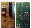
I have a number of phase angle controller PCBs and found that the triacs have failed,I have replaced the triacs and PCBS work perfectly.

I would welcome any thoughts / suggestions on why these triacs could be failing ,is it a cheap component / PCB design / wrong triac used ???

Any would be brilliant,

Thanks Darren.
 

Attachments

DickCappels

Joined Aug 21, 2008
10,171
Consider a latent manufacturing defect or a poorly specified part as possible reasons. I don't see a snubber on that circuit board so it is possible that high rates of change between the main terminals caused damage if the wiring and load were sufficiently inductive. Since the diacs used to fire the triac can have different firing voltage for positive and negative half cycles, a load such as a motor or transformer primary could cause a large DC component to exist that would increase the triac's power dissipation. That's for starters.
 

Thread Starter

aspiespot

Joined Dec 14, 2018
21
Consider a latent manufacturing defect or a poorly specified part as possible reasons. I don't see a snubber on that circuit board so it is possible that high rates of change between the main terminals caused damage if the wiring and load were sufficiently inductive. Since the diacs used to fire the triac can have different firing voltage for positive and negative half cycles, a load such as a motor or transformer primary could cause a large DC component to exist that would increase the triac's power dissipation. That's for starters.
Hi ,
Thank you very much for your reply , I would like to fit a snubber to the circuit,I have read a number of articles online and tried my best to work out the components and values to use .

At this stage the formula is a bit above my skill level,

would anyone be able to point me in the right direction or even better advise of exactly what components and values to use,

The input is 230v,

thanks very much,

darren.
 

sghioto

Joined Dec 31, 2017
5,390
From the photo the snubber circuit appears to consist of the missing components C2 and R2. Common values I've seen are .1uf/600v for C2 and 100ohm/2watt for R2.
SG
 
Top