 Facebook
 Google
 GitHub
 Linkedin
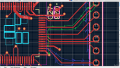
Ads1299 on left.
MCU input pins on right.
SPI signals going between them on layer 1
Layer 2 is a ground plane
0.11mm dielectric between planes
Frequency of signals is around 60mhz. 8ns rise time.
DOUT is GREEN and returns to DGND pin on the ADS1299
DIN is BLUE and returns the the MCU GND pin on the top of the picture out of frame.
I am having a hard time understand how the return paths can literally intersect across each other and not cause a ton of issues.
The traces are spaced more than enough for their frequency. It's just the returns paths.
Attachments
-
 581.3 KB Views: 12


