Facebook
 Google
 GitHub
 Linkedin
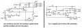
Yes, but a redesign without the transformer that functions identically would be worthwhile, wouldn't it? Don't ask me to do this. A low-power transformer with a center-tapped primary is very uncommon, I would say.The transformer is a very much integral part of the circuit. It provides the feedback to make the circuit oscillate. So there is no way the posted circuit can possibly use a 555 or am LM386 as substitutes.
ALSO, transformers are still used, but not usually for audio amplifier outputs. So a low-power transformer, 200 to 500 ohms primary impedance, center tapped, to 8 ohms, or 10 ohms secondary impedance, should work.
A NOTE TO ALL: the TS did not ask for a redesign that would be entirely different!!
What would be a suitable transformer for this circuit?
- Thread starter RoabeArt
- Start date