I have this page in SYN155 datasheet. I want to know what power do I need to run this module because I want to build a low power WSN powered by a solar harvester. What power do I need to consider in designing the circuit? Ho
I want to build a low power WSN powered by a solar harvester. Here is a photo from SYN155 datasheet. What power do I need to consider for this module in building the circuit? The transmission will be simplex if it does matter.
It is hard to fathom how this device could be compatible with a low power environment. You can ignore the power dissipation figure under Absolute Maximum Ratings, since that power level will destroy the device. You have two power supplies with two different voltage levels and different power requirements. The two together require 920 mW. That is what you should design for.
While the real answer to your question is power profiling if we take the datasheet on its face, the worst case seems to be 920mW, which is not very low power. Nor is a 5V supply requirement a good thing for solar power.
It is hard to fathom how this device could be compatible with a low power environment. You can ignore the power dissipation figure under Absolute Maximum Ratings, since that power level will destroy the device. You have two power supplies with two different voltage levels and different power requirements. The two together require 920 mW. That is what you should design for.
It was very cheap in the first place. But I think I will go with this https://www.farnell.com/datasheets/301334.pdf if you don't mind checking it out. Or if you have suggestions about how I should choose a better module I will be very grateful.
I know this is not necessarily what you want to hear, but if you want to maximize your chances of success, please take this seriously.
I think your process is upside down. You really need to create a list of requirements and then specify the components. You might have to change the specs as you find what is and what is not possible, but choosing the radios before deciding what they need to do is not going to end well.
Some things to consider:
What is your monetary budget? Unless it is open ended, you will have to make tradeoffs n specifying components. If you have only an informal idea of the budget you are likely to
What is the nature and capacity of your “solar harvesting”? This will determine things like:
Physical size of the completed device
Location
Maintenance
Cost, of course
What is your time budget? This will decide things like:
The possibility of saving money by building yourself instead of buying
Alternatively the necessity of buying to save the time of building
The importance of parts availability and delivery dates
What kind of power budget will you have with that setup? This will determine things like:
Hours of operation
Data rate
Transmission frequency (interval, not radio frequency)
Practical distance from base
But before all of this, you need to draw some pictures (block diagrams, high level network diagrams) and write a narrative about how you expect the system to behave.
Start with stating the problem you are trying to solve. This is critical. You have to clearly articulate what success will look like. If the system “works” what problem will have been solved?
Then sketch out a general description of the solution. You can and should include how user interaction will work if there is any. Stories about what it will be like to use it are best, they help identify missed problems and requirements.
You don’t have to do this excessively formally but you have to have some idea of the moving parts because as you can see if you consider the list, they all interact and creating a requirements list is an iterative exercise in prioritization and optimization.
After you have some version of this done, you can choose a radio, and power equipment, and a hardware/software platform for processing. I will be happy to help you with that if you have a reasonably orderly and complete requirements list. Otherwise, it’s all guessing.
Physical size: I’ll like it as small as possible (I don’t have an answer here since the solar panel takes a lot of space).
Location: Indoor
Maintenance: Wouldn’t matter that much, it’s a project, it’s not crucial for a business or something like that. It only has to work when I present it to show that it can be done.
Cost: I can go like 200-300 euros, maybe even more.
Time budget:
I would try to implement as much as possible. It’s a university project, so it would be great to do everything from scratch if its not close to impossible, since I will learn a lot of things. Time is not tight, I have like 4 months. I have to make a documentation as well and everything has to be very well rounded.
Power budget:
Transmission frequency: In my mind I’ll have a thermometer, a humidity sensor, a VOC sensor, and a battery monitoring circuit. I would like to send each parameter every 10s ( and if a very high variation is detected, every 1s, if it’s possible and not too hard to implement in regard of hardware, not software, because it depends if I can power it to transmit that often). I have to have a battery of at least 700 mAh. As a MCU I’ll use a low power PIC.
Practical distance from base: minimum 100m direct visibility
Hours of operation: It has to have at leas 12 hours of autonomy
Data rate: I don’t know how to take this in consideration.
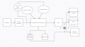
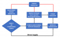
My narrative: Collect the solar panel energy, regulate it. Then feed it to a power management block where the voltage is stepped up and the surplus energy is stored in a battery. A supply enabler commanded by a custom pulse generator (that generate pulse signal that enables the current to go to the MCU-this should work like a automatic switch in my opinion) will power the MCU and the sensor that will send the data which will be displayed on a 16x1/2 LCD (it depends how many characters I need).
I hope I covered everything.
OK, so I am going to suggest a couple of things to start. Since your budget is reasonably large and it is a two node network, consider LoRa as the the radio/protocol. It is designed for low power operation, it has all the facilities to manage error detection and correction, and it can be expanded to many more nodes very easily. There are even public satellites that support it.
The second thing is that you watch a few videos from Andreas Spiess, whose LoRa and low power content is excellent. It will get you into a position to start asking specific questions and filling in the block diagram with actual parts for implementation.
Here is one of his videos to get started, but if you check his channel you will find many relevant topics.
By the way, once you have more information about what will be needed, I am more than happy to help you make it work. I am sure there are others here who are also ready to help. It just needs a starting point from you. The description and diagrams are very helpful in understanding what you want to do, but they are not set in stone, be ready to change them entirely as needed.
OK, so I am going to suggest a couple of things to start. Since your budget is reasonably large and it is a two node network, consider LoRa as the the radio/protocol. It is designed for low power operation, it has all the facilities to manage error detection and correction, and it can be expanded to many more nodes very easily. There are even public satellites that support it.
The second thing is that you watch a few videos from Andreas Spiess, whose LoRa and low power content is excellent. It will get you into a position to start asking specific questions and filling in the block diagram with actual parts for implementation.
Here is one of his videos to get started, but if you check his channel you will find many relevant topics.
Hi and sorry to bother you again! I'm set up for the most hardware part. I have a 5.9V/304mW/61mA solar cell (it's pretty small and has a weight of only 25g) that goes into a solar battery charger with MPPT (found it very cheap for like 5 euros so I said why not, I only need to change a SMD resistor to change the max charging current) that outputs 4.2V so I can charge a 1000mAh LiPo battery (the battery will be charging at a rate of 0.06C). Also I'll use 2 Schottky diodes and a p channel power MOSFET on the output to power the PIC+sensors+LoRa and to charge the battery (simultaneously) when I have enough power from the solar panel (when the sun is up and shining). The battery will go then into a fixed 3V voltage regulator (Low drop-out regulator that has a very low quiescent current). Now the thing is I need to use SPI communication (I know how to do that) with LoRa, and for compatibility between PIC and LoRa I need at least 128 kB flash memory and 8 kB RAM on the PIC part. I found PIC18f27Q43 that meets this requirements and uses nanoWatt XLP technology so I can consume even less power using deep sleep mode. The problem is that I don't find PIC18f27Q43 in mikroC to write the code and compile the hex file so I can load it into the MCU and also I don't find a compiler in MPLAB (I found the PIC, but not a compiler for it), do you have any other suggestion on what and how to program the PIC18f27Q43? As sensors I'll use an accelerometer, humidity +temperature sensor and a battery monitoring circuit. I'll send this information to a RPI 4 that I'll program as a data server with a web interface so I can save and visualize data and when certain parameters exceed a threshold value the RPI 4 will send a SMS to some phone numbers (eg: battery is critically low or the target is moving South, North, East, West and the acceleration and maybe a GPS module so I can get the position aswell but I might exceed the power budget and it's pretty hard to do).
Is the rating of your solar panel in full sun? You said it would be indoors, which means the solar panel might produce only a few percent of its rated power.
Is the rating of your solar panel in full sun? You said it would be indoors, which means the solar panel might produce only a few percent of its rated power.
There are specially designed indoor and outdoor solar cells from Panasonic, I chose an outdoor panel that will work outdoor, the requirement list for the project doesn't say it should be indoor or outdoor. The indoor ones doesn't go past 250 uW so I have to use an array of cells if I would want to power the circuit and they would occupy way too much space, same with RF harvesting (I designed a G Shaped Cuff Button Antenna that's omnidirectional and has dual resonance band to harvest the RF energy, but it provides like 1- 0.x uW so it's no use) because LoRa consumes 16-25 mW of power when it is in Tx mode. Also, even if the sensors are indoor, I can find a way to put the panel outside and the circuit inside. I didn't graduate my bachelor's yet so I don't need to reinvent things, it's only about the learning process and doing something that can be of use in some situations.
Edit: Thanks for asking, indeed I said in the earlier messages that it would be indoor but I couldn't find an Tx/Rx module, even if it's Bluetooth or LoRa ( I need to transmit the data for at least 100 m) that would need so little power so that I can power it from an indoor solar cell/panel. The sensors and the MCU doesn't consume that much power, the modules that transmit data do.
 Facebook
 Google
 GitHub
 Linkedin
 Ho
Ho