What kind of LEDs are these?

Thread Starter

GRNDPNDR

Joined Mar 1, 2012
545
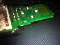
In this picture, the grouping of SMD LED's, can anyone identify which type of SMD LED they are? I need to replace them with ultra bright blue leds and need to find which leds to purchase as a replacement. Ignore the red circle, its for something else.
 

Attachments

wayneh

Joined Sep 9, 2010
18,135
In this picture, the grouping of SMD LED's, can anyone identify which type of SMD LED they are? I need to replace them with ultra bright blue leds and need to find which leds to purchase as a replacement. Ignore the red circle, its for something else.
Is that board working? You could disconnect one LED and measure the current it’ Being supplied and that will greatly reduce your search.
 

Thread Starter

GRNDPNDR

Joined Mar 1, 2012
545
Is that board working? You could disconnect one LED and measure the current it’ Being supplied and that will greatly reduce your search.
I ddon't currently have that board, but will have it soon. It's for my truck but I haven't gotten the truck yet.
I've done this mod before in my last truck with the same parts, but I never got around to these SMD LED's.

What I do know is that it's a vehicle, so it's running at 12-15VDC.
I don't think it matters much which LED is used, so long as I can find one of the same size, in bright blue. I'll be able to measure the physical size when I get the truck.
 

wayneh

Joined Sep 9, 2010
18,135
I don't think it matters much which LED is used, so long as I can find one of the same size,
I think you’ll find that size is not a defining characteristic of an LED. There may be many of the same size with different specifications.
 

Thread Starter

GRNDPNDR

Joined Mar 1, 2012
545
ok so I got a hold of a board to re-work, but what I need to find out is the value of the resistor thats to the right of the red circle.
It looks like it says 721, can anyone confirm?

The voltage is about 12-15VDC, and these are SMD LEDs so probably 3.3VDC correct? So what resistor would I need to put in that spot?
 

wayneh

Joined Sep 9, 2010
18,135
721 would likely be 720 ohms, 72 plus one zero. That would be about right for a typical LED at 12-15V. That’s an inefficient way to drop that voltage but I guess efficiency is not a big concern. You can confirm the ohms value with a cheap multimeter.
 

Thread Starter

GRNDPNDR

Joined Mar 1, 2012
545
721 would likely be 720 ohms, 72 plus one zero. That would be about right for a typical LED at 12-15V. That’s an inefficient way to drop that voltage but I guess efficiency is not a big concern. You can confirm the ohms value with a cheap multimeter.
I have a multimeter, how would I go about confirming the value with it?
Likely it is a 721 resistor, efficiency doesn't matter really in vehicle applications, from what I can determine there is one resistor that provides the voltage drop for all 4 SMD LEDs. so I just need to find the right value, drop in LEDs (if I can find the correct polarity) and be done with it.
 

ebp

Joined Feb 8, 2018
2,332
It is hard to tell from the photo, but think it is probably 220 ohms - 221. 220 ohms is a common value, 720 ohms is not. It could also be 122 - 1200 ohms, which is also a common value. If the LEDs run from a nominally 12 volt automotive system, 1200 ohms would yield around 8 to10 mA of LED current. Lots of blue LEDs are really bright at 10 mA. That is for one LED lit at a time. If they are all in series, 220 ohms would make more sense.

Running 4 blue LEDs in series is a dicey proposition with 12 volts - 4 x 3.3 = 13.2 volts. This makes current limiting with a resistor a problem because there is no voltage across the resistor at 12 volts and 1.8 V at 15 V. If you scale the resistor for acceptable current at 15 V, the LEDs will be very dim to off as you get down toward 12.

If the odd shaped pads are for touch switches with conductive "rubber" inserts, be sure the pads are cleaned thoroughly. It is easy to get a bit of flux spatter and flux can interfere with such switches working reliably. I recommend 99% isopropyl alcohol (flammable, but otherwise reasonably safe for you and the board) and cotton swabs.
 

wayneh

Joined Sep 9, 2010
18,135
I have a multimeter, how would I go about confirming the value with it?
Set your multimeter scale and just put a probe on each side of it. It might have something in parallel with it that distorts the reading, but that’s unlikely if it’s really the current limiting resistor.

It’s unlikely that the LEDs are in parallel and sharing a single resistor. That would be a poor design. Are they typically all on at the same time?

If you can test the board while it’s powered, you could get the voltage drops across the LEDs, across the resistor, and even the LED current if one is removed.
 

MisterBill2

Joined Jan 23, 2018
28,077
To determine the resistance of a component attached to a system with semiconductor devices it is very useful to check with both polarities, in case there is some kind of junction across the item. The higher reading is more likely to be right. But if it is an external light, such as a stop, turn, or backup, or even a headlight, then a series resistor would not have adequate current carrying capacity , most likely. The assembly may also use an external driver circuit.. LED devices are very unforgiving of excess current and voltage, by the way.
And those vacant pads may easily be for more LED devices in a different application.
 

Thread Starter

GRNDPNDR

Joined Mar 1, 2012
545
This is a window control switch from a truck, There are about 3 different revisions that I've seen. These pads are for the mirror switch so it will also be lit up.

One model has green LEDs pre-installed, that's what's in the picture in this post.
The second model has absolutely no option, pads or anything for LEDs and is not illuminated at all.
The third model is what I'm currently working with, it has no LEDs but has the pads for them to be installed, it was just never done at the factory.

They are wired in series from that resistor, that's how auto manufacturers do it so if one light goes out they all go out. it doesn't have to be efficient.

The brightness of these LEDs never changes, there's no dimmer switch for them or anything, they're fed a constant voltage from the vehicles electrical system, which is anywhere from 12-14.5VDC.


All I need to do here is identify which resistor I should be using in that spot, which LEDs to use, and the polarity of those pads on the circuit.

I'll get some more pics when I'm back to working on it later.
 

Thread Starter

GRNDPNDR

Joined Mar 1, 2012
545

Attachments

Thread Starter

GRNDPNDR

Joined Mar 1, 2012
545
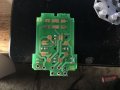
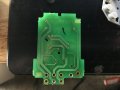
Here's other pics of the board.....although I think I have it mostly figured it out now, I just have to find the right size and wavelength of LEDs to match the rest.

Positive is circled in red, ground is in black. I was looking at another LED light that I have that uses smd's on it for automotive applications and it's using a 220 resistor also, so I'm fairly certain that it should be a 220 on this board as well..... in fact I may even be able to cannibalize the LED light to use it's SMD's and maybe resistor..... I have no damn idea how I'm going to solder that onto the board.
 

Attachments

Thread Starter

GRNDPNDR

Joined Mar 1, 2012
545
I have the LEDs that I pulled off another light, they're ever so slightly too large but the contacts fit right on the pads.

So I'm thinking the easiest way to solder these on to the board would be to toss it into the oven......but before I do that, is it a bad idea? I don't have a datasheet so I don't know what t he max temp for the LEDs are.

as for the resistor, there's actually enough room that I wouldn't need to use an SMD, and could just use a regular resistor.
 

Thread Starter

GRNDPNDR

Joined Mar 1, 2012
545
I got the LEDs soldered on and they work great at 12V, so I'm assuming I won't need a high value of resistor to account for the additional voltage when the vehicle is running.
 

MisterBill2

Joined Jan 23, 2018
28,077
The process would be to determine the size and brightness of the devices, and figure out what the package style is. Once you have the package style numbers and the light intensity and color it is a matter of checking with different LED makers as to what they offwer in that package style.
But I am wondering, is this for a production program, or a one-off customization project? That does matter a lot to the suppliers, they would much rather sell you 10,000 parts.
 

Thread Starter

GRNDPNDR

Joined Mar 1, 2012
545
it's a one off customization to my truck. I got the SMDs installed and working, I just need to sort out the right resistor, which I think should be 220ohms
 

MisterBill2

Joined Jan 23, 2018
28,077
220 ohms should work, it is a reasonable value and a very common one as well. And if you have the room to use a standard resistor, they have more surface to dissipate heat and so are the better choice,
 

wayneh

Joined Sep 9, 2010
18,135
They are wired in series from that resistor, that's how auto manufacturers do it so if one light goes out they all go out. it doesn't have to be efficient.
That works fine, much better than parallel, and offers decent efficiency. The down side is what you've noted - it's like a string of christmas lights. And not all LEDs will light on 12V with 4 in series. It sounds like yours do, so you should be all set.
 

wayneh

Joined Sep 9, 2010
18,135
it's a one off customization to my truck. I got the SMDs installed and working, I just need to sort out the right resistor, which I think should be 220ohms
That will work, but so would 270, 330, 390 or 470Ω. It just depends how bright you want them. You might be able to go as low as 100Ω and still be in spec for your LEDs but don't try that without working up to it. Chances are it'll be plenty bright with any of those other values. The higher the value resistor you use, the less likely you are to age the LEDs with voltage spikes.
 
Top