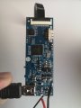
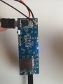
What is the purpose of this connector?

Thread Starter

Netskyes

Joined Oct 17, 2017
6
Hey all, so I've a circuit of this mini wifi camera and it stopped working, I'm not receiving image anymore (probably tape camera module died).
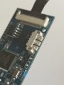
Anyways, can someone help me figure out what that unused connector is there for?
This is a chinese mini wifi camera.

(White one, 4 mini pins)
Does anyone know anything about this circuit, can this be reused somehow, reprogrammed?
Thanks!IMG_20190602_160602_1.jpg IMG_20190602_161005.jpg IMG_20190602_161015.jpg
 

narkeleptk

Joined Mar 11, 2019
599
TP usually stands for Test Point.
It looks like its used for testing, Or maybe even just there for when maker first programmed the device and they labeled it TP instead of J
 

Tonyr1084

Joined Sep 24, 2015
9,744
I agree with Test Point. But usually all test points are labeled as TP1, TP2 and so on. Looking the board over, there are no other TP's listed. It's possible all four pins of the connector are test points, but logic would dictate a connector used as a test point, usually either TP1 and 4 would be listed or all four. IF for some reason they only wanted to list one of the four leads as test points (assuming all four pins are TP's) they would most likely have listed TP1.

It's not clear what the connector is for. I thought of another possibility, it could be Test Programming point #4. But I can't tell if the connector you're holding is HDMI or USB. If it's USB then most likely that would be the port where they upload the programming. But if it's HDMI then they might need a programming port. But then why would they have four (at least 4) programming points.

If you look at the far side of the board away from the connector you see G, RX and TX pads. Those look like traditional test points to me. However, over the years I've seen many different style test points. Those pads are most common with "Bed Of Nails" test equipment, where they lay the board on a bed of nails (strategically positioned), press down on the board and run diagnostic tests to make sure the board passes specific requirements at each point.

If the connector was not being used in the end product it may either be something there to make manufacturing easier - OR it may be a connector for a feature the camera might have in a higher model. In other words, your car doesn't have cruise control, but there are connectors there for it. Sometimes the reason for that is ease of manufacturing. It's easier to make a single harness that can handle all features whether the car is equipped with them or not. The difference is what's plugged into them. So if it was unused it may be simply something that is there should the manufacturer decide to upgrade the board to add a feature, easily added in with programming.

@narkeleptk referred to "J" as a connector designation. That's also very common. J and P, where J (if I recall correctly) stands for a female connector and P stands for the male mate.
 

Ya’akov

Joined Jan 27, 2019
10,307
Given the size of the pins and connector, I would guess it is for a battery. The TP4 legend doesn't really make sense, it's not in the write place, and the other connector is marked "J1" as a connector would be.

Can you trace the positive power connection and see if it runs there, or check continuity from the positive (without power connected) and the pins?
 
Top