 Facebook
 Google
 GitHub
 Linkedin
Hi
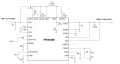
Trying to figure this regulator out (see link). But I have difficulty with "compensation network" for "loop stability" (pin 18 "COMP" and page 39 in the datasheet)
What exactly is the "compensation network"? what does it compensate for? how does it work?
Anyone that can help me out with understanding this concept?
https://www.ti.com/lit/ds/symlink/t...ed-dc-dc-switching-regulators%2Foverview.html
Attachments
-
 70.4 KB Views: 13


