What Is Probably Wrong With This Circuit?

Thread Starter

abrogard

Joined Dec 20, 2018
77
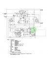
I have an old Yamaha electronic organ. And it just broke. Main amplifier Fuse 3 blows all the time. I wonder if anyone could look at the circuit and give me their opinion of what might be causing it?
 

Attachments

drc_567

Joined Dec 29, 2008
1,156
The diagram shows two 2200 uF/63 volt electrolytic capacitors adjacent to the fuse and transformer. If you desolder and remove the two capacitors, then carefully apply power momentarily and see if F3 blows or not. Aging electrolytic capacitors fail occasionally. Note the + and - polarity marks on each capacitor and their installed orientation.
 

Thread Starter

abrogard

Joined Dec 20, 2018
77
The diagram shows two 2200 uF/63 volt electrolytic capacitors adjacent to the fuse and transformer. If you desolder and remove the two capacitors, then carefully apply power momentarily and see if F3 blows or not. Aging electrolytic capacitors fail occasionally. Note the + and - polarity marks on each capacitor and their installed orientation.
Thank you. I will see if I can do it. I've added some more pictures to the imgur post so's you can see where the board is. At the bottom left hand on a big metal chassis. I think I will have to take it out to get at the things on it.

If I do that will it still operate for testing purposes? I mean I guess those big 'output' and 'input' things would need to be connected so it wouldn't work if they weren't?
 

drc_567

Joined Dec 29, 2008
1,156
... the two electrolytic capacitors could be what is wrong with it. If you remove them and apply power, the test will be whether the F3 fuse fails. If that fuse does not fail with the capacitors removed, then you may conclude that one or both of the capacitors has shorted out. Replace both of the capacitors, noting polarity markings .... Mark + and - on the circuit board. Turn the power on and see if anything else turns up.
 
Last edited:

ebp

Joined Feb 8, 2018
2,332
The capacitors may well be "worn out" but this will not normally increase the current, and as far as a fuse (a resistor) in the input path is concerned will likely decrease the RMS current.

How the fuse fails can provide useful clues. If it blows "immediately" when power is applied, it is likely that there is a short-circuit somewhere. If it blows after a period of seconds to minutes, it is likely that something is drawing excessive, but not grossly excessive current.

The unregulated output of that section probably feeds the audio amplifier, so it is not unlikely that the problem is in the amplifier and not something in this schematic at all.
 

Thread Starter

abrogard

Joined Dec 20, 2018
77
It doesn't blow immediately. About 30 seconds perhaps. It is a 'slow blow' fuse though.

I've done nothing yet. Was waiting for perhaps a remark on taking it out. Will it operate for testing purposes outside of the cabinet with those two plugs - input and output - removed?

But I've since realised I can quite easily sit it back in there and plug it in after desoldering or whatever so that's no longer a worry. I'll go about getting it out.

I simply remove the capacitors and apply power? And leave the wire open circuit? We're talking about the capacitors marked 2200/63?
I don't understand those figures, either, by the way. :)

Maybe the audio amp? I have the service manual. I'll look up the audio amp circuit if I can.

Test the transistors. How? I don't have a CRO. What could I use, how can I do it? I talked to the only serviceman for these things in the whole of south australia, so he was telling me, and he told me you can't use a CRO for trouble shooting these boards. He's kinda saying that CRO's are just for digital circuits.

I'm very ignorant but I thought you could use a CRO on anything and that they're perfect for probing around boards like this and just checking you've got what you should have where it should be... ?

They haven't got an app to make a CRO out of your cellphone do they?
 

drc_567

Joined Dec 29, 2008
1,156
.... not completely confident that the two electrolytic capacitors are what is wrong. There are one or two additional current paths that could easily be what is causing F3 to fail.
 

ebp

Joined Feb 8, 2018
2,332
Even with slow blow fuses, a full short circuit would cause them to below within a couple of seconds. Slow blow (time delay) fuses are common in circuits where capacitors are to be charged to allow the initial charging current. If the inside of a glass tube fuse is black or black and silver, the fuse was blown due to very high overcurrent. If the fuse element is visible and just has a small gap in it or looks like it sort of drooped and melted into 2 or more pieces, the overcurrent was likely not more than a few times the fuse rating.

2200/63 means the capacitors are 2200 µF (microfarads), rated for operation at up to 63 volts DC (these weird values like 63 V are "historical", and make little sense).

You can probably find the fault with just a multimeter. Usually things that cause something like a blown fuse are fairly "obvious" in an electrical sense and not something that requires looking at waveforms. People who are very experienced in using oscilloscopes will often use a scope where others might use a meter and in so-doing gain some extra information from their measurements, but that doesn't mean the scope is strictly necessary. For example, I could measure a voltage on a capacitor in a power supply with a meter and get an average DC voltage that looked OK, but if I used a scope I might see higher ripple voltage than I would expect, which might point to the capacitor nearing the end of its useful life.

I just realized that what I looked at casually without thinking about it IS the audio power amplifier. I glanced at it and thought it was a voltage regulator. Stupid me. The circuit in question is the bunch of components in the center at the top of the posted schematic. That is almost certainly where the problem is. DodgyDave's suggestion is a good starting point, though given the time it takes to blow the fuse I think the problem may be a bit further back in the circuit.

One thing that happens in amplifiers is that the thermal "grease" that is often used between the power transistors and the heatsink "dries out" - typically a silicone oil in the stuff evaporates over time. This impairs the heat transfer and the transistors heat up. If a part that senses the heating can't because it doesn't get heated, the "bias current" in the amp can rise to where it might well blow a fuse.

Does the fuse blow even if you don't try to play, or do you get some sound for a few seconds then the fuse goes? Did the speaker make a loud "clunk" before the fuse blew that it didn't make in earlier life?
 

dendad

Joined Feb 20, 2016
4,474
Add an incandescent mains lamp (40W or so) in series with the mains. That will limit the current and may help you find the problem.
Or, you could put a 24V tail light lamp in place of the secondary fuse. It will allow the amp to power up to some extent, but limit smoke. You will not be able to run the amp at any power levels like that, but it will be enough for you to test things without running through a lot of fuses.
 

Thread Starter

abrogard

Joined Dec 20, 2018
77
For a few seconds I can press a key and get a proper note. The thing's working fine. It wouldn't be 30 seconds though, at a guess.

The blown fuse I took out was just a broken wire, not black anywhere. It was just a wire, too, whereas the 'slow blow' that I bought to replace it are like little springs wound around a core. I don't know if that means the first was wrong or the second is wrong or what.

Yes, I wondered about the 'amp' thing and just imagined there must be another little amp in there somewhere I didn't know about.

I don't know why I thought a multimeter was no good for troubleshooting electronic circuits. A vague memory of some dangers of distorting the circuits somehow with a multimeter? I don't know. But if it's okay then that's good.

Test how? Voltage test. Put the neg on the earth and just test for voltages around the transistor, each side of resistors, diodes - what about capacitors - can they be tested in situ with a multimeter?

What voltages shall I look for when checking those transistors, 6 and 7?

If I take the thing out of the cabinet so's I can get at it I won't be able to plug the 'input' and 'output' plugs in. When the board is energised by plugging the power in I'll still be able to make meaningful readings even without the in and out plugs? Or I've got to find some other way?
 

dendad

Joined Feb 20, 2016
4,474
What is your multimeter?
With power off, test the diodes in D1 and D2.
testing diodes in circuit can give you some odd readings, but you should be able to detect is one is shorted.
 

ebp

Joined Feb 8, 2018
2,332
The fact you can get a note for a bit says that lots of things are OK! It does make me more suspicious of some sort of bias point shifting, which would alllow too much DC current straight through the output of the amp between the +32 V and - 32 V rails.

I'm going to have abandon you for now, I've prematurely run out of steam today.
 

JoeJester

Joined Apr 26, 2005
4,390
Do you have the page on what is connected to US2-S? F3 also goes to whatever circuits that might be connected via that connector.
 

JoeJester

Joined Apr 26, 2005
4,390
Can you snap a picture of the back of the elephant ear speaker magnet where the model number and other numbers appear?
Can you snap a picture of the tag showing the model number of the organ?

You say it takes 30 or so seconds before the fuse blows. Were you pressing any keys at the time? What is the position of the volume control and balance control?

The problem I have is your fuse is too small for a 30 W system.
 

Thread Starter

abrogard

Joined Dec 20, 2018
77
It is a BK7I. I'll take a pic when I get a chance. Just saw this today:

Add an incandescent mains lamp (40W or so) in series with the mains. That will limit the current and may help you find the problem.
Or, you could put a 24V tail light lamp in place of the secondary fuse. It will allow the amp to power up to some extent, but limit smoke. You will not be able to run the amp at any power levels like that, but it will be enough for you to test things without running through a lot of fuses.
I'll have a go at that when I get down to working on it. It's a good idea?
 
Top