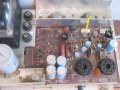
There appears be staining around the blue electro on the top picture.
Measure the resistance across them to see what the reading is. But from the age of the unit, I'd advise replacing them all anyway.
Also, check for shorts across the diodes "BL" and "RE".
I am making some progress. Found B– and B+ . I think.
B– goes to the 0.47Ω resistor on the brown wire from pin 9 on that circular thing and B+ has an orange wire going to one of those 200mF electrolytic capacitors. Right?
I thought I'd made a good pic this time but looking for that on my pic it wasn't so good. The board marking is actually obscured by the wire. I might try make a better pic.
It is a good idea to place a couple of layers of tape over all the mains power terminals on the strip so to make it a little harder to touch. And anywhere else the mains is exposed.
The 2 large electros will be the B+ and B_- supplies. There will be a connection between them, one to a +Ve and the other -Ve, and that is the 0V reference line. The B+ and B- can be measured from that line, and it is probably connected to the chassis, to each of the other electro caps pins. The one with the black mark will be -ve usually. But you can check that from the marking on the plastic sleeve.
Yes, it is a bit hard to see in the photos.
That's a good and important tip about the tape, thanks, I wouldn't have thought of it.
Haven't found that 'reference line' connection between them yet. But not that important I guess, I can do the measurements with what I've already found and the tips I've been given.
Ok, you found the test points by the wire color, that's good.
Have you reviewed how to test a diode?
Have you made the resistance checks?
Since the lamp energized immediately, there is a short. I'm sure F3 would have blown if you didn't have that lamp. So lets do some resistance checks to see where we can direct the troubleshooting.
Remember ... NO power is applied during the resistance checks. Keep the AC cord away from the AC receptacle. Report back when you tested the B+ and B- to chassis ground resistance. Chassis ground is the G or Ct point on the schematic or the black wire on the big 2200 uF capacitors.
After you make and report the resistances. Read on how to test a diode and transistor using a DMM (digital multimeter). Where are you located for parts availability.
Well I've done some resistance tests.
The numbers vary considerably and generally seem to constantly climb.
That means to me that there is a resistance and not a short and so I take the probe away and report the number I was at then.
Seems very important to get the tip of the probe in exactly the right place. I guess the solder is perhaps covered with enamel or something and the right place is where it gets through to the metal.
I got:
Black meter lead on Ct: B- -1.6
B+ 7
Red meter lead on Ct: B- 3.4
B+ -3
For Ct or Ground I used the connection of the black lead at the very top right corner or your picture there. That black lead runs from the cap you've put a couple of rectangles on and it solder to the board and nothing else. There's no component there. No track. Nothing. It's just a point. So I used it for an earth point.
I used for B- and B+ the points indicated on the board. i.e. the left hand point in the rectangle in your picture for B- and the hidden orange wire connection in your picture. Hidden under the red wire.
I didn't plug it in and fire it up. I'm not sure about safety. I rest my hand on the chassis to make those unpowered resistance checks. When it is live I suppose I must avoid touching the chassis?
And earlier you said ".. power up, wait a minute, ensure lamp is not energized.." before doing live voltage tests.
Well I know the lamp will be energized. It energizes not when I plug everything together but as soon as I switch the organ on. I would expect that because I'd expect current to flow even if the volume is set to minim. But apparently you don't expect or want it.
So I await your advice about: 1. touching the chassis and 2. doing live tests if the lamp is lit.
p.s. I just went back and measured B+ across the terminals on the cap indicated by your rectangles, in case that's a better way.
Meter black to black on the cap: 6 and climbing.
Meter red to black on the cap: -3 more or less stable.
Is there zero ohms between the chassis and the capacitor tab marked "G" in the picture above? If so, the chassis can be used as the reference point for a lot of the measurements.
Can you get a better picture to see the terminals of both electrolytic caps?
It is a good rule of thumb to have one hand in your pocket while working on live chassis. That is a bit hard most of the time. And no, there is no need to hold onto the chassis. In fact, if you get your other hand in the wrong place, that can be very dangerous.
Measure the resistance from the cases of each power transistor to the chassis. It should not be a short.
Then from the transistor case to the 0.47ohm resistor connected to that transistor. That is a easy way to test the Collector (case) to Emitter not shorts. It should not be a short.
I'll go take better pictures and I'll check between G and the chassis. But '..marked G..' ? I think i know which you mean but I don't see a mark there... ? You mean the black wire to the capacitor with the two rectangles he's added?
I did see your remark about diodes BL and RE but didn't do anything about it because it confused me. BL and RE refer to the wire colours, I think, don't they? 'Black' and 'Red'. So I looked for diodes that were perhaps right next to a 'BL' and an 'RE' sign but didn't see them.
Could you perhaps indicate which diodes they are on the circuit diagram in some other way and I might find them?
Thanks for the tip about the chassis.
I just plugged everything in to check I was right about the lamp lighting and I was. It lights up immediately I switch the organ on and stays alight while I wait a minute or two.
Check for C to E short on the other transistor too. I did not mark that as it is not really visible in the photo.
Of course, you can try to check for the short at the transistor pins and mounting screw from the other side if that is easier.
I checked the transistors and I get various readings but no dead shorts.
Now I see what you mean about the BL and RE diodes. Sorry. My mistake. I was looking underneath the circuit board and on the circuit diagram - anywhere but right there on the top where they're clearly labelled.
I can test them now but can I ask you how to do it? Googling around I keep getting useless info about two leg diodes detached from the board. It'd be quicker to just ask you.
@dendad you will need to tell the TS how to execute each test you want the to do. Explain how to test the diode. Identify the points you want the TS to do, how to set it up, everything. The TS is inexperienced by their own admission.
@dendad have you found a datasheet with a pinout of the 10DC-2 and 10DC-2R diodes so you can help him.
What you wanted tested was described in post 2. The post before mine is 52.
Here is a pretty good intro to multimeters from Spark Fun.
See if that helps you.
On the circuit, it shows the diode pairs (D1 and D2) so just test them as a couple of diodes with the center pin common. Note that they are not the same. On pair is common cathode, while the other is common anode.
And yes, The "BL" and "RE" are the wires but the labels are near the diodes so I put that in to help you identify them.
Okay. Thanks. I just don't know what a three leg diode is. Two legs is straightforward enough. This way should be infinite resistance, the other way should be none. More or less?
But what do I look for on three legs?
When I google they keep showing me stuff about two leg diodes.
I'll look at the video.
Meanwhile I found apparently no resistance between the casing of this transistor and either leg of this resistor - does that signify anything? And I suppose it won't hurt if I just measure either way from the centre on the diodes and across from the outside.
Okay. Measured the diodes.
The Black one on the 20K range shows 1 from the centre to either leg with the black lead on the centre.
It shows -3 from centre to either leg with the red lead on the centre.
It shows zero either way from outside leg to outside leg.
The Red diode is the same except it shows about -6 with the red lead in the centre out to either leg.
Does your multimeter have a diode test?
The diodes should read 0.7V or there abouts in the forward direction, and open in the other. Test from the center pin to one outside one, then reverse.
Next, from the center pin to the other outside pin for the second diode.
Note that the RED double diode is connected in the reverse direction to the BLACK one.
But I think it more likely the output transistors will be the problem. So see if you can measure them. They can be treated as a double diode just like the rectifiers. The Base to Collector and Base to Emitter each behaves as a diode so the same test can be applied. Just remember, the reading in circuit can be different as there are other parts connected that will change the readings. http://www.svntc.com/TPDF/1829.pdf
On page 3 of this data sheet, it shows the connections. 1 = base, 2 = Emitter and 3 = Case = Collector.
I think perhaps I've asked a bit more than I thought I was going to, here. I'm much appreciative of the patience you are showing and I'm trying to do my bit down here. It's true I've come from a long way behind.
I do have diode measurement on the multimeter.
I used it and the diodes seem alright, I think. I got similar measurement on each.
They were:
Black diode: Red lead on centre - to each of the other legs: meter showed '1'.
Black lead in centre to each of the other legs: meter showed '390' for each.
Bed diode: Red lead in centre meter showed '390' to each of the other legs.
Black lead in centre meter showed '1' to each of the other legs.
Using the same measurement thing on the multimeter I tried two of the power transistors.
Tr7 Red lead on the Base: '303' to the emitter, '1' to the collector.
Black lead on the Base: '330' to the emitter, '1' to the collector
Tr6 Red lead on the Base: '320' to the emitter, '340' to the collector.
Black lead on the Base '329' to the emitter, '500' to the collector.
 Facebook
 Google
 GitHub
 Linkedin
")