 Facebook
 Google
 GitHub
 Linkedin
Hello,
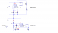
Attached is a simple prototype of remote control system with one channel consisting of a transmitter and its receiver.
i have tried getting it to work without success.........what could be wrong?,i have been playing around it for two days now.
Kindly assist.
regards
Attached is a simple prototype of remote control system with one channel consisting of a transmitter and its receiver.
i have tried getting it to work without success.........what could be wrong?,i have been playing around it for two days now.
Kindly assist.
regards
Attachments
-
 16.4 KB Views: 49


