What are terminals I and R used for on this alternator?

Thread Starter

Jopee

Joined Jun 30, 2024
41
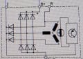
This is a Cummins alternator (24V 95A). I would like to know what are terminals "I" and "R". How are they used? I am guessing terminal "I" turns on the regulator? I have no clue about terminal "R".

Edit. Part ID for that alternator is 4944732.
 

Attachments

Last edited:

LowQCab

Joined Nov 6, 2012
5,101
If You are using the Alternator for some other application than it was designed for,
You don't need the "R" terminal.

The "I" terminal should go to an Incandescent-Light-Bulb which is then attached to Ignition-Power.

The Light-Bulb should turn "On" when the Ignition is "On" and the Alternator is NOT providing Power.

The Light-Bulb should turn "Off" when the Alternator starts providing Power,
or any time the Ignition-Switch is "Off".

The Alternator Senses the Battery-Voltage at the point where the Ignition-Power is received.

The Voltage at the point where Ignition-Power is received by the Alternator may not be
exactly the same as the Voltage right-at the Positive-Battery-Terminal,
it will likely be slightly less due to Wiring-Resistance and any
Electrical-Loads being applied to the Ignition-Power-Source at that point.
This is an important understanding if You have any Charging-Voltage discrepancies,
and You are trying to diagnose the Charging-System.
The "I" Terminal should be connected as close as practical to the Ignition-Switch.


The Charging-Voltage, with the Battery fully charged,
should be between ~28-Volts and ~29-Volts under ideal circumstances.

If the "I" Terminal is left completely disconnected,
The Alternator "may" still work acceptably well,
but the Charging-Voltage at the Battery may be slightly lower than is desired,
AND/OR,
the Alternator may not "start" charging until the Engine RPM has been
"revved-up" to ~3000 to ~4000 RPM at least one time, before the Alternator will "Self-Start".
The Alternator will then continue to operate normally until the Engine is stopped.
.
.
.
 
Last edited:

MisterBill2

Joined Jan 23, 2018
27,394
In addition to the previous comments, that circuit shown in post #1 is not complete. Consider that it does not include any connection shown to allow current to flow thru the rotating field. So the whole circuit is a partial functional illustration. It does show the indicator connection, which is also the battery voltage sensing connection. so it will tend to be a bit misleading.
 

Thread Starter

Jopee

Joined Jun 30, 2024
41
So that means the alternator will still work if you don't use terminal I. Even though R terminal is not used in that picture I would still like to know what it is. If anyone knows?
 

LowQCab

Joined Nov 6, 2012
5,101
If You are installing this Alternator in anything besides the original application,
DO NOT connect anything to the "R" Terminal.

It has a special use in the original application ONLY.
.
.
.
 

Thread Starter

Jopee

Joined Jun 30, 2024
41
If You are installing this Alternator in anything besides the original application,
DO NOT connect anything to the "R" Terminal.

It has a special use in the original application ONLY.
.
.
.
This was kinda pointless answer. Google gives lots of different answers like R terminal is voltage sense, relay output, excite and so on.
 

LowQCab

Joined Nov 6, 2012
5,101
Gosh !!! What results !!! so exactly what function does it serve ????

Only people who have the original Factory-Schematic of the Vehicle it was designed for have a clue.

The "R" Terminal does not serve the same function on every Alternator.

On the Schematic You provided, "R" serves no useful generic function.
.
.
.
 

MisterBill2

Joined Jan 23, 2018
27,394
So that means the alternator will still work if you don't use terminal I. Even though R terminal is not used in that picture I would still like to know what it is. If anyone knows?
I would not promise that it will work without terminal I being able to sense the system voltage. If it will work without a series light bulb is not obvious, but certainly the "B" terminal is not a sensing terminal. The "R" terminal will deliver a voltage with a lot of ripple , which cam verify that the alternator is working. It would be useful for a belt break sensor circuit.
 

LowQCab

Joined Nov 6, 2012
5,101
Sorry I can't be of much help, but it's interesting that the R terminal is going to be an AC voltage coming off of only one winding.
.
This is incorrect .......
The "I" terminal will have an Output that is very close to identical to the Batt-Terminal.
The only differences between the 2 is the difference in the respective Forward-Voltage-Drops
caused by the fact that they are physically different part-numbers,
and with different amounts of Current being drawn from their respective groupings of 3.

Both sets of 3-Diodes, "I", and "Batt", will each Output a standard 3-Phase Waveform,
which has a minimal, and very predictable, amount of Ripple.

The "Batt" Output may have slightly less Ripple than the "I" Output because the "Batt" Output
is directly connected to the actual Battery,
which "acts-like" a giant Capacitor,
and the "I" terminal has a much longer, and smaller gauge, Wire connecting it to the Battery,
which means that there is much more Resistance in it's path to the Battery.
.
.
.
 
.
This is incorrect .......
The "I" terminal will have an Output that is very close to identical to the Batt-Terminal.
The only differences between the 2 is the difference in the respective Forward-Voltage-Drops
caused by the fact that they are physically different part-numbers,
and with different amounts of Current being drawn from their respective groupings of 3.

Both sets of 3-Diodes, "I", and "Batt", will each Output a standard 3-Phase Waveform,
which has a minimal, and very predictable, amount of Ripple.

The "Batt" Output may have slightly less Ripple than the "I" Output because the "Batt" Output
is directly connected to the actual Battery,
which "acts-like" a giant Capacitor,
and the "I" terminal has a much longer, and smaller gauge, Wire connecting it to the Battery,
which means that there is much more Resistance in it's path to the Battery.
.
.
.
I feel like something got Lost in translation here. When I said "I" I meant literally me. Me, the person, I can't be of much help, and I'm sorry that I can't be of much help. I never referenced the I terminal, I only referenced the R terminal, which appears to connect directly to one of the windings, unrectified.
 

Thread Starter

Jopee

Joined Jun 30, 2024
41
Gosh !!! What results !!! so exactly what function does it serve ????

Only people who have the original Factory-Schematic of the Vehicle it was designed for have a clue.

The "R" Terminal does not serve the same function on every Alternator.

On the Schematic You provided, "R" serves no useful generic function.
.
.
.
If you don't know the answer to the question I asked then say you don't know or don't reply at all. You saying I don't need to connect anything to the terminal doesn't help anyone.
 
Last edited:

LowQCab

Joined Nov 6, 2012
5,101
I feel like something got Lost in translation here. When I said "I" I meant literally me. Me, the person, I can't be of much help, and I'm sorry that I can't be of much help. I never referenced the I terminal, I only referenced the R terminal, which appears to connect directly to one of the windings, unrectified.
.
Sorry, I should have quoted Mr.Bill's post, I just mixed-up the two posts.
.
.
.
 

LowQCab

Joined Nov 6, 2012
5,101
If you don't know the answer to the question I asked then say you don't know or don't reply at all. You saying I don't need to connect anything to the terminal doesn't help anyone.
.
It's not because I "don't know the answer",
it's because no one knows the answer,
as You found-out with your own search efforts.

Possibly go back and re-read this entire Thread, You may have missed some things.

I later stated most emphatically DO-NOT connect "R" to anything.
This is based on my experience with Alternators,
and, with my experience with reading Schematic-Diagrams.

Schematic-Diagrams mean specific things, and convey specific information.
The "R" terminal is of no practical use in a generic-application according to the Schematic-Diagram.

Of course there is always the possibility that You provided a random Schematic-Diagram
that does not accurately reflect the actual Alternator that You are working on.
That could really throw a wrench into the gears and cause all sorts of confusion.

Further explanations were given,
as to some of the common peculiarities of "old-school" domestic Alternators.
( even some of the newer Computer-controlled ones still use these antiquated letters for odd purposes )

It's a good-bet that You are dealing with a very common AC-Delco Alternator,
which have had the exact same letters cast-into the Cover since around the ~1970s,
even though there have been at least ~4 different Wiring-configurations used.

You have been given excellent advice based on your presented Schematic.
If You don't "like" the answers given, You are in no way obligated to listen to any of it.

I hope that You may have learned something useful,
and that, You keep in mind that You paid nothing for it.
.
.
.
 

MisterBill2

Joined Jan 23, 2018
27,394
I HAVE looked at quite a few of those original vehicle circuit schematic diagrams! So I AM aware of what is going on. IF you are able to look at that original posted circuit of the alternator and understand it, you will see that the "I" terminal also is tied to the voltage regulator portion that controls the rotating field excitation. So that connection is rather important to the alternator function. Also understand that as it is shown with three diodes tied to the same windings, that is not exactly correct, but in reality is quite similar to how it really is. The "I" terminal also provides the start-up excitation power for the alternator, as well as serving to sense the voltage being delivered to the battery. And the "R" terminal would indeed be useful to provide an indication of the alternator Rotating. Very useful for systems that need to know that.
 

Thread Starter

Jopee

Joined Jun 30, 2024
41
I HAVE looked at quite a few of those original vehicle circuit schematic diagrams! So I AM aware of what is going on. IF you are able to look at that original posted circuit of the alternator and understand it, you will see that the "I" terminal also is tied to the voltage regulator portion that controls the rotating field excitation. So that connection is rather important to the alternator function. Also understand that as it is shown with three diodes tied to the same windings, that is not exactly correct, but in reality is quite similar to how it really is. The "I" terminal also provides the start-up excitation power for the alternator, as well as serving to sense the voltage being delivered to the battery. And the "R" terminal would indeed be useful to provide an indication of the alternator Rotating. Very useful for systems that need to know that.
Yeah I know how an alternator works. "The Engineering Mindset" has a good video about it. I did see that "I" terminal is tied to the voltage regulator. That's why I guessed that it turns on the voltage regulator. So basically if you don't supply 24 volts to the "I" terminal then the alternator doesn't produce any charging voltage to the battery. Okey so the "R" terminal is stator pulse which can be used for a tachometer for example.

Good post.
 
Last edited:

MisterBill2

Joined Jan 23, 2018
27,394
How did we suddenly get to 24 volt alternators?? I doubt that feeding 24 volts to a 12 volt alternator will result in it changing to 24 volts. BUT I HAVE NEVER TRIED IT. And I still much prefer the arrangement with a separate voltage regulator. I can replace an external MOPAR regulator in about 3 minutes. For less than $20 (at that time). The last time i checked, for an internal reguator the alternator was replaced about $175 and a half hour's work.
 

LowQCab

Joined Nov 6, 2012
5,101
24-Volts was specified in Post#1.
The cost of the Internal Regulator depends mostly on who's name is on the outside of the box,
in this case the name is Cummins, which jacks the price to the moon.
It's kinda like buying a complete Alternator for an old Chevy-Impala, and it costs ~$79.oo,
but if You tell them that it's for an old Corvette, the price jumps to ~$487.oo, for the exact same Alternator.

The major difference between a 12-Volt and a 24-Volt Alternator
of the make and type that "I believe" we are discussing here, ( old-school- Large-Case Delco-Remy ),
is the Rotor-Winding, the maximum-Amperage-Rating of the Alternator, and the Internal-Regulator,
all other parts are identical and interchangeable.

The 12-Volt-Rotor-Winding draws roughly ~5-Amps max.,
the 24-Volt version draws around ~2.5-Amps max..

On this particular style of Alternator,
they do require disassembly to replace the Regulator,
but it's a relatively simple job with a 5/16ths Nut-Driver and a Paper-Clip to hold the Brushes for reassembly.
That is IF I'm correct about the make and type of Alternator.
.
.
.
 
Top