 Facebook
 Google
 GitHub
 Linkedin
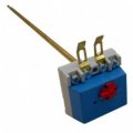
I’m working on connecting the resistor/heating element of my boiler, and I’m using the thermostat shown in the photo below. From what I understand, this is a 4-pin thermostat.
I measured continuity with an ohm-meter and found the following:
I connected one terminal from the left pair and one terminal from the right pair with the heating element. When I switch ON the circuit breaker on the electrical panel, the resistor heats up and the water starts warming. When I switch the breaker OFF, everything stops. So far, it behaves exactly as expected.
My question is:
What are the other two unused terminals on this 4-pin thermostat supposed to be connected to?
Any explanation about the typical wiring and function of these 4-pin boiler thermostats would be very helpful.
Thank you!
I measured continuity with an ohm-meter and found the following:
- The two terminals on the left have continuity with each other.
- The two terminals on the right also have continuity with each other.
- Left and right sides are not connected to each other.
I connected one terminal from the left pair and one terminal from the right pair with the heating element. When I switch ON the circuit breaker on the electrical panel, the resistor heats up and the water starts warming. When I switch the breaker OFF, everything stops. So far, it behaves exactly as expected.
My question is:
What are the other two unused terminals on this 4-pin thermostat supposed to be connected to?
Any explanation about the typical wiring and function of these 4-pin boiler thermostats would be very helpful.
Thank you!
Attachments
-
 44 KB Views: 18


