Facebook
 Google
 GitHub
 Linkedin
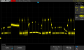
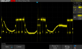
I'm confused by your post #15 Oscope captures. RS422/485 should nominally have 2.5 volts as a virtual ground. If I'm interpreting your scope capture, it's swinging positive and negative with as you say 0.4v the nominal ground reference. What am I missing here? As long as you're staying within in the common mode ability of the receiver, RS485 is extremely error free bit rate. But that does require your ground references between the bus transceivers to have a low impedance reference to this common ground. If DC currents and spikes from switched loads is causing IR drops that exceed the common mode receiver's ability, then you will have bit errors. What size ground wire is connecting the +5/+12 supplies from their source? And what current spikes are the remote slaves switching. Or am I totally misunderstanding your problem here? If the remote slaves are connected to some local ground that could have negative effects if that has large offsets between these units. This could be offsets from the AC mains power ground currents (neutral wire offsets).You can see the bus released when it gets back to a +0.4V or similar between the messages, as the result of the fail-safe bias. I did not replace the power supply of the master and slaves, I replaced a power supply for different purposes. And though I see that the new power supply is causing my trouble I just do not understand why.
On edit, is the scope ground reference giving some offset to the bus signal?
Last edited: