When I close the circuit with water which raises the resistance it reflects on the base of the transistor ,which in return raises the voltage above 0.7V turning off the reset pin and turning on the alarm?Now does the electric current flow from base to collector or from emitter to collector to pin4?
I'll bet if you measure it, as you dip that board into water ... and the water contacts both strips of foil (+ and -), the resistance should decrease. But you would need a meter to do that.
The test described earlier, by connecting a 100k in series with the sensor and that combination across a power source, would come to the same conclusion.
Here is the schematic.Its working but I'm not sure why its not making the siren noise it just makes a continuous siren sound it doesn't go up and down in volume?
The LED/Resistor/Capacitor connected to pin 5 will not affect the volume. It will affect the frequency. 555 oscillation is based on the trip points of two internal comparators. Current into or out of pin 5 moves both trip points, but one more than the other.
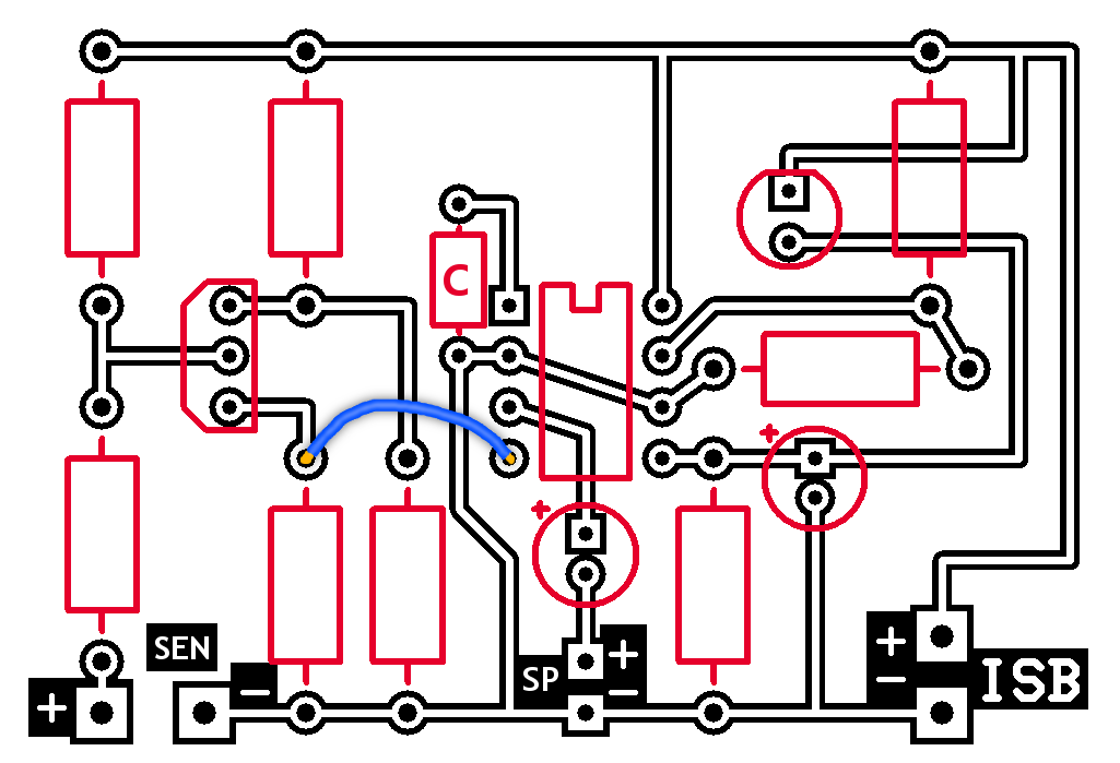
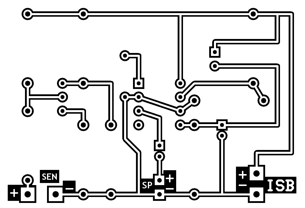
Here is the PCB design in case someone wants to try it out on a PCB.You need to connect the wire from PIN 4 to the resistor's line because i wanted to keep the board on one layer.

 Facebook
 Google
 GitHub
 Linkedin