Watch a voltage level and when it drops below 5v, supply power to something

SamR

Joined Mar 19, 2019
5,519
Take it a step further. Learn to program the AT chip without all the Arduino bells and whistles. Or, use a Nano.
 

Reloadron

Joined Jan 15, 2015
7,897
Just changed the fuel pump in my wife's 99 Tahoe which includes the fuel level sensing unit. It's just a pot configured with a float. One problem with these devices, even when baffle enclosed is the voltage out, proportional to fuel level, is not always stable. What happens is when the tank reaches for example a 5.0 VDC return from the sensor pot that 5 volts bounces around a little. So for example if I use a uC (micro-controller) or discrete components the LED you want to illuminate will flicker as the return signal voltage hovers around that 5.0 volt level. Most automotive fuel gauges compensate with some form of dampening. Using a uC or discrete components electronically we call it Hysteresis which with a uC is done in software and using discrete components is done with a form of feedback in a circuit. You may wish to consider that whatever road you take.

Ron

PS To the guy who posted the diagrams of exactly where to lift the carpet and make a cut to remove the pump less having to drop the fuel tank many, many thanks. You are my hero! :)
 

Thread Starter

scythe944

Joined Jan 30, 2021
12
Take it a step further. Learn to program the AT chip without all the Arduino bells and whistles. Or, use a Nano.
I might do that, just want to get something functional as quick as possible first, and I have the Arduino on hand. I know it's way overkill and would like to simplify the project later and the AT chip looks to be what I'd need in order to do so.
 

Thread Starter

scythe944

Joined Jan 30, 2021
12
Just changed the fuel pump in my wife's 99 Tahoe which includes the fuel level sensing unit. It's just a pot configured with a float. One problem with these devices, even when baffle enclosed is the voltage out, proportional to fuel level, is not always stable. What happens is when the tank reaches for example a 5.0 VDC return from the sensor pot that 5 volts bounces around a little. So for example if I use a uC (micro-controller) or discrete components the LED you want to illuminate will flicker as the return signal voltage hovers around that 5.0 volt level. Most automotive fuel gauges compensate with some form of dampening. Using a uC or discrete components electronically we call it Hysteresis which with a uC is done in software and using discrete components is done with a form of feedback in a circuit. You may wish to consider that whatever road you take.

Ron

PS To the guy who posted the diagrams of exactly where to lift the carpet and make a cut to remove the pump less having to drop the fuel tank many, many thanks. You are my hero! :)
Thanks Reloadron, I did imagine that there would be some stability issues, and I brought that up to my buddy whom I'm trying to build this for, he didn't seem to mind if it flickered a bit when it was close to the level. I was thinking about trying to do some sort of dampening in the code, sort of put a delay in the voltage check for a few seconds and only power the LED if after say, 10 checks within the last 15 seconds returned a voltage of 5V or lower, and only then, turn the LED on, but that's probably (definitely) over my head.
 

PRASS

Joined Feb 22, 2018
31
scythe944
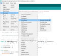
Here is the example also in the Arduino IDE that you would need to switch the LED on. (pictured below)
This will make the LED go bright or dim depending on the battery level.
If you want the LED to just turn on or off; there is a line of code that says,
outputValue = map(sensorValue, 0, 1023, 0, 255);
If you change the 0 to LOW & the 255 to HIGH or vise versa in your case it will just just switch on or off.

I have tweaked this basic code for you in a file I have copy pasted below.
When you copy paste it into IDE, go to full screen & you will see the modifications I have made compared to the basic code written in //CAPITAL LETTERS next to the added code.
I have given some brief instructions on how to add your own code also for anything else you may need.

I hope this helps out

analog in out.png


// These constants won't change. They're used to give names to the pins used:
const int analogInPin = A0; // Analog input pin that the battery is attached to
const int analogOutPin = 9; // Analog output pin that the LED is attached to

int sensorValue = 0; // value read from the battery
int outputValue = 0; // value output to the PWM (analog out)


int RELAY = 6;
// HERES WHERE I PUT IN ANOTHER FUNCTION TO SWITCH THE CIRCUIT ON/OFF OR CONNECT A RELAY ON DIGITAL PIN 6
// YOU CAN PUT AS MANY DIFFERENT FUNCTIONS AS YOU WANT HERE USING THE SAME int RELAY =........ BUT YOU WILL HAVE TO CHANGE THE PIN NUMBERS TO HOOK UP TO


void setup() {
// initialize serial communications at 9600 bps:
Serial.begin(9600);


pinMode (RELAY, OUTPUT); //HERE IS WHERE I DEFINED THE PINS PURPOSE
digitalWrite (RELAY, LOW); //THIS IS JUST SETTING THE PIN TO LOW or OFF IN OTHER WORDS SO THE RELAY ISN'T ALWAYS ON FOR NO REASON
}


void loop() {
// read the analog in value:
sensorValue = analogRead(analogInPin);
// map it to the range of the analog out:
outputValue = map(sensorValue, 0, 1023, 0, 255);
// change the analog out value:
analogWrite(analogOutPin, outputValue);


if (outputValue < 100){digitalWrite (RELAY, HIGH);} // THIS IS THE MAIN BIT OF THE CODE WHERE I HAVE TOLD THE PROGRAM IF THE VOLTAGE DROPS BELOW THE DESIRED THRESHOLD TO TURN ON pin 6 THE RELAY

//THE OUTPUT VALUE IS BETWEEN 0 & 1023. . . . .I HAVE WRITTEN 100 AS AN EXAMPLE BUT THIS NUMBER WILL NEED TO BE CHANGED TO SUIT YOUR DESIRED VOLTAGE.


// print the results to the Serial Monitor:
Serial.print("sensor = ");
Serial.print(sensorValue);
Serial.print("\t output = ");
Serial.println(outputValue);

// wait 2 milliseconds before the next loop for the analog-to-digital
// converter to settle after the last reading:
delay(2);
}
 

Thread Starter

scythe944

Joined Jan 30, 2021
12
scythe944
Here is the example also in the Arduino IDE that you would need to switch the LED on. (pictured below)
This will make the LED go bright or dim depending on the battery level.
If you want the LED to just turn on or off; there is a line of code that says,
outputValue = map(sensorValue, 0, 1023, 0, 255);
If you change the 0 to LOW & the 255 to HIGH or vise versa in your case it will just just switch on or off.

I have tweaked this basic code for you in a file I have copy pasted below.
When you copy paste it into IDE, go to full screen & you will see the modifications I have made compared to the basic code written in //CAPITAL LETTERS next to the added code.
I have given some brief instructions on how to add your own code also for anything else you may need.

I hope this helps out

View attachment 229196


// These constants won't change. They're used to give names to the pins used:
const int analogInPin = A0; // Analog input pin that the battery is attached to
const int analogOutPin = 9; // Analog output pin that the LED is attached to

int sensorValue = 0; // value read from the battery
int outputValue = 0; // value output to the PWM (analog out)


int RELAY = 6;
// HERES WHERE I PUT IN ANOTHER FUNCTION TO SWITCH THE CIRCUIT ON/OFF OR CONNECT A RELAY ON DIGITAL PIN 6
// YOU CAN PUT AS MANY DIFFERENT FUNCTIONS AS YOU WANT HERE USING THE SAME int RELAY =........ BUT YOU WILL HAVE TO CHANGE THE PIN NUMBERS TO HOOK UP TO


void setup() {
// initialize serial communications at 9600 bps:
Serial.begin(9600);


pinMode (RELAY, OUTPUT); //HERE IS WHERE I DEFINED THE PINS PURPOSE
digitalWrite (RELAY, LOW); //THIS IS JUST SETTING THE PIN TO LOW or OFF IN OTHER WORDS SO THE RELAY ISN'T ALWAYS ON FOR NO REASON
}


void loop() {
// read the analog in value:
sensorValue = analogRead(analogInPin);
// map it to the range of the analog out:
outputValue = map(sensorValue, 0, 1023, 0, 255);
// change the analog out value:
analogWrite(analogOutPin, outputValue);


if (outputValue < 100){digitalWrite (RELAY, HIGH);} // THIS IS THE MAIN BIT OF THE CODE WHERE I HAVE TOLD THE PROGRAM IF THE VOLTAGE DROPS BELOW THE DESIRED THRESHOLD TO TURN ON pin 6 THE RELAY

//THE OUTPUT VALUE IS BETWEEN 0 & 1023. . . . .I HAVE WRITTEN 100 AS AN EXAMPLE BUT THIS NUMBER WILL NEED TO BE CHANGED TO SUIT YOUR DESIRED VOLTAGE.


// print the results to the Serial Monitor:
Serial.print("sensor = ");
Serial.print(sensorValue);
Serial.print("\t output = ");
Serial.println(outputValue);

// wait 2 milliseconds before the next loop for the analog-to-digital
// converter to settle after the last reading:
delay(2);
}
@PRASS Thank you so much!!!! This is awesome. If it works, I'd gladly give you some money for your efforts.

Is it okay to put 12V to PIN A0? I'm scared that I might fry the board.
 

Reloadron

Joined Jan 15, 2015
7,897
@PRASS Thank you so much!!!! This is awesome. If it works, I'd gladly give you some money for your efforts.

Is it okay to put 12V to PIN A0? I'm scared that I might fry the board.
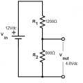
No, the maximum analog in with a 5 volt Arduino Uno for example is 5 Volts. Typical automotive systems I like using a 3:1 divider network, just a few resistors. I have also just used a 10K pot across the automotive voltage and adjusted the pot for my desired output. I would use a 10K pot. Rtotal in the above divider is 2 K which I would not use. Your voltage is coming from the wiper in the fuel tank. You do not want any loading effect on that sending unit. Not if you want to accurately know the fuel level anyway. I just do not see the above as a good choice. It would be nice to know the full and empty voltage values. Keep in mind also a 12 volt automotive system varied between about 12.6 volts to 14.5 volts or greater.That's why I like a 3:1 divider ratio.

Ron
 
Last edited:
Top