Voltage Regulator Circuit / LM-317T

Thread Starter

Gabriel Gourmet

Joined Nov 18, 2021
7
Hello,
I'm not sure if this is the best place to post this question but here it goes. Also I'd just like to point out that I am a complete beginner. I will clarify to the best of my ability if clarification is needed.
I'm a student in college and i'm part of a electrical engineering group. Now I've been tasked with building a voltage regulator circuit with an input of about 8 volts and an output of 5V and 1.5A. The output would be used to power a Raspberry Pi microcontroller.

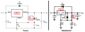
Using the internet and PSpice, I managed to configure the following circuit using an LM-317T voltage regulator.220 + 2x330..PNG
Now upon testing in person, at first I burned out the 3.3 Ohm resistor because that was definitely too much current going through but for a little bit the reading were correct (i.e. around 1.5A and 5V).

Finally here is my question: Is this a proper circuit to power a Raspberry Pi microcontroller if connected before the 3.3 Ohm resistor or is it bad because of the small resistor value?
If not, what would be a good alternative?
I'd just like to point out a few things:
-firstly, someone told me that the 3.3 ohm resistor only acts as a sort of shunt resistor to measure the current but when I change its value on PSpice it also changes the current, therefore I'm not sure.
- secondly, I've already tried an LM7805 regulator but could not get the 1.5A output desired, probably due to my inexperience.

Thank you for any help you can provide.
 

BobTPH

Joined Jun 5, 2013
8,812
The 3.3Ω resistor is what we call a “dummy” load, for testing only. You do not use any resistor between the output of the LM317 and the real load. If you were to put a resistor in series with the load, it would defeat the purpose of the voltage regulator. Think about it. If any current flows through a resistor, it would drop a voltage as calculated by Ohm’s law. Then the voltage on the load would not be 5V, would it?

Bob
 

Thread Starter

Gabriel Gourmet

Joined Nov 18, 2021
7
The 3.3Ω resistor is what we call a “dummy” load, for testing only. You do not use any resistor between the output of the LM317 and the real load. If you were to put a resistor in series with the load, it would defeat the purpose of the voltage regulator. Think about it. If any current flows through a resistor, it would drop a voltage as calculated by Ohm’s law. Then the voltage on the load would not be 5V, would it?

Bob
I see yes, I wasn't thinking about that. Thank you for the fast answer.

I do have a follow up question then: Last time I measured for current I did get the 1.5A but only got about 2V output. I checked all my components and they were fine.
What could have caused that? (the very first time I measured I'm pretty sure I got the 5V).
 

ericgibbs

Joined Jan 29, 2010
18,766
hi GG,
Consider the power dissipation in the LM317. Look up thermal shut down.

8Vsuppy - Vout = 8V -5V =3V across the LM317 at 1.5Amp = 3V*1.5A = 4.5Watts.

Check the LM317 data sheet

E
 

BobTPH

Joined Jun 5, 2013
8,812
Yep, if you are going to draw 1.5A through an LM317, you need a heatsink. Also, is your 8V supply capable of 1.5A at 8V?

Bob
 

Thread Starter

Gabriel Gourmet

Joined Nov 18, 2021
7
Yep, if you are going to draw 1.5A through an LM317, you need a heatsink. Also, is your 8V supply capable of 1.5A at 8V?

Bob
Yes, the one our group has for testing is capable 1.5A. And you're absolutely right, I am using a heatsink.

So besides potential faulty components, what could be a cause of a wrong output voltage from the LM317? (in my last measurement: 2V)

I think in my case the reading could have been off because of a faulty resistor but I wanted to know if there were other possible reasons.
 

BobTPH

Joined Jun 5, 2013
8,812
I would test the power supply at 1.5A and measure the voltage. I'll bet it is not 8V any more.

Also, with your regulator, measure the input when it is putting out 1.5A. It really needs to be 8 to regulate at 5.

Bob
 

Thread Starter

Gabriel Gourmet

Joined Nov 18, 2021
7
I would test the power supply at 1.5A and measure the voltage. I'll bet it is not 8V any more.

Also, with your regulator, measure the input when it is putting out 1.5A. It really needs to be 8 to regulate at 5.

Bob
Understood, I will test for that and see.
Thank you very much for your fast answers.
 

Thread Starter

Gabriel Gourmet

Joined Nov 18, 2021
7
I would test the power supply at 1.5A and measure the voltage. I'll bet it is not 8V any more.

Also, with your regulator, measure the input when it is putting out 1.5A. It really needs to be 8 to regulate at 5.

Bob
Actually, while I'm at it. I was looking through the LM317 datasheet and I saw this circuit:diode_lm_317.PNG
I was thinking of possibly building as I believe it could offer some better protection but the diodes shown are only good for up to 1A.

Now I'm also completely new to diodes and I tried watching a few videos but I didn't quite understand how to choose an appropriate diode for a circuit.

So in my case, if I still want 5V and 1.5A output, what diode could I use in this circuit?

Thank you,
Gabriel.
 

crutschow

Joined Mar 14, 2008
34,282
I am using a heatsink.
How large a heatsink?
What is its thermal resistance to air?
I believe it could offer some better protection but the diodes shown are only good for up to 1A.
Why do you think you need higher current diodes?
D1 protects the LM317 by discharging Vo if the input voltage suddenly drops to 0V.
D2 discharges Cadj if the output suddenly drops to zero.
 

dl324

Joined Mar 30, 2015
16,845
I was thinking of possibly building as I believe it could offer some better protection but the diodes shown are only good for up to 1A.
Those diodes only carry current when the capacitors discharge. Your caps aren't large enough to cause damage so they're not required.
 
Last edited:

ericgibbs

Joined Jan 29, 2010
18,766
hi dl324,
I agree, ref the diodes for the 'demo' project, but we don't know what extra capacitance will be added within an actual load.

E
 

Audioguru again

Joined Oct 21, 2019
6,673
You copied a datasheet circuit with a different IC, the more expensive LM117 that uses 240 ohms for R1. The LM317 needs 120 ohms. Then you need a pot with half the value that was calculated to be with the 240 ohms.
 

Attachments

Top