 Facebook
 Google
 GitHub
 Linkedin
Hi All,
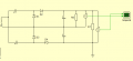
I am designing an SMPS and have an issue with my output voltages. I am using a voltage quadrupler to boost my transformer output by 4x. I will attach a schematic of the multiplier rectifier to this thread.
My issue is that, although I expect 800V and 400V at my output for the two loads, they are quite imbalanced. I get 829V and 407V, which is quite the difference. I have tried multiple changes to my schematic but the imbalance seems to remain. The diodes are ideal, as are the capacitors.
Any suggestions for these discrepencies would be appreciated!
Capacitors are 100nF each.
Attachments
-
 7.6 KB Views: 18


