A real working driver is needed for signal from 74AC14 to voltage multiplier

Thread Starter

Rhou

Joined Feb 8, 2025
7
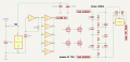
A real working driver is needed for signal from 74AC14 to voltage multiplier via drivier.
Supply 5 Volts from 278R05. on one element 74AC14 create generator 583Khz.
Next 5 triggers connect in paralel for more current value.
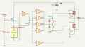
output signal need connect to driver (2 or 4 mosfets) on IRF7319 (P-channel and N-channel in one package).
driver connect to voltage multiplier x6 VCC. Next connect to stabilizer L7812, and need output about 50mA current.
need driver circuit witch IRF7319.
Not working driver sample I attach:
 

Attachments

schmitt trigger

Joined Jul 12, 2010
2,027
Your circuit is still incomplete. While we may guess at your intention, the incomplete circuit prevents us from suggesting anything other than only speculations.
But if you want to understand Mosfet gate drive ICs, please read the following:

https://www.allaboutcircuits.com/te...-new-gate-driver-ic-from-diodes-incorporated/

EDIT: I have re-read your first post, and there you mentioned that you would like to multiply the 5 volt input 6 times, and then regulate it down to 12 volts.
Why would you even want to do that in the first place?
 
Last edited:

Thread Starter

Rhou

Joined Feb 8, 2025
7
Your circuit is still incomplete. While we may guess at your intention, the incomplete circuit prevents us from suggesting anything other than only speculations.
But if you want to understand Mosfet gate drive ICs, please read the following:

https://www.allaboutcircuits.com/te...-new-gate-driver-ic-from-diodes-incorporated/

EDIT: I have re-read your first post, and there you mentioned that you would like to multiply the 5 volt input 6 times, and then regulate it down to 12 volts.
Why would you even want to do that in the first place?
I need get 12 volts and 50mA from 5 volts supply.
 

Irving

Joined Jan 30, 2016
4,996
Works but only 50% efficient and generates peak pulse currents of 8A+ on 5v supply. And you need 8-stage to get 3v headroom for a 7812. Use a 1W pre-packaged DC-DC converter instead, or if you want to roll your own, there are many sub-$1 chips eg TI LM2735, see below.

1758991570372.png

LM2735 example
1758992356575.png
 

Thread Starter

Rhou

Joined Feb 8, 2025
7
Works but only 50% efficient and generates peak pulse currents of 8A+ on 5v supply. And you need 8-stage to get 3v headroom for a 7812. Use a 1W pre-packaged DC-DC converter instead, or if you want to roll your own, there are many sub-$1 chips eg TI LM2735, see below.

View attachment 356512

LM2735 example
View attachment 356513
yes, I know about dc/dc converters. but need create with irf7319. need very simple : how connect this 4 mosfets for like by multipier for bigest current. without driver, only on ic 74ac14 I get about 2mA. need driver.
 

sparky 1

Joined Nov 3, 2018
1,218
The boost converter current is from the inductor's magnetic field,
In this video shows output fix for the MT3608. fast forward video to 10:25
if current limiting is needed then the duty cycle can help.


A 7414 used to make a voltage tripler with input 5V, RC for 583kHz is 470pF and 1.6K, 15V regulated to 12Vdc@20mA
an LC pair for 583kHz is 10uF and 7.46nF used to tame the noise discussed in an earlier video.

In the video he tries more complex and expensive converters repairing one he uses the tweezers alot but in the end
he settles for the cheap one, he understands the noise is less and the price is less.
 
Last edited:

0ri0n

Joined Jan 7, 2025
160
A Dickson charge pump is shown below. Needs a complementary drive, in this case without resorting to non-overlapping clocks. Clock frequency is 100kHz. Efficiency is good with low average transistor dissipation. Using integrated MOSFET drivers instead of discrete transistors would simplify things.

Dickson_Charge_Pump.png
 
Top