Facebook
 Google
 GitHub
 Linkedin
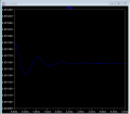
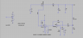
I am trying to design a simple buck converter. But it doesn't work as expected. Output voltage should be 19V but it is very close to input with value 48.5V. Also there is a problem with pwm generator. If anyone could help,I will appreciate for it.Thanks.
Attachments
-
 16.4 KB Views: 6
 -
 11 KB Views: 8
 -
 24 KB Views: 9
 -
 24 KB Views: 8