I am stuck at design a circuit with the specs as below.
Input voltage: VDD
Output voltage: Vout
VDD is also the ONLY power supply for the circuit.
When VDD = 1V, Vout = 0V
When VDD = 2V, Vout = 2V
Any idea how this can be done without using IC?
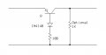
Draw a simple transistor circuit - common emitter configuration.
Put a suitable resistor in the emitter leg to ground that keeps current to a safe level for the transistor you use.
Oh, Use NPN. Connect Vdd straight to collector.
You need to prevent your base voltage from turning on the transistor when Vdd is 1 volt but let enough voltage through when Vdd is 2 volts to forward bias the base.
Do you know how much voltage 2 diodes in series drop when forward biased?
Draw a simple transistor circuit - common emitter configuration.
Put a suitable resistor in the emitter leg to ground that keeps current to a safe level for the transistor you use.
Oh, Use NPN. Connect Vdd straight to collector.
The answer depends on the type of diodes.
For silicon diodes, the typical forward voltage is 0.7 volts, so two diodes in series will drop about 1.4V.
For germanium diodes, the forward voltage is only 0.3 volts, so two diodes in series will drop about 0.6V.
It will take one PNP transistor, one diode and two resistors (or one resistor depending on the load.) I'll give you a hint; the emitter is connected to the input. Can you figure it out??
I am stuck at design a circuit with the specs as below.
Input voltage: VDD
Output voltage: Vout
VDD is also the ONLY power supply for the circuit.
When VDD = 1V, Vout = 0V
When VDD = 2V, Vout = 2V
Any idea how this can be done without using IC?
I am stuck at design a circuit with the specs as below.
Input voltage: VDD
Output voltage: Vout
VDD is also the ONLY power supply for the circuit.
When VDD = 1V, Vout = 0V
When VDD = 2V, Vout = 2V
Any idea how this can be done without using IC?
You haven't given enough information. You've said what you want Vout to be at just two particular values of Vdd. What about all of the other values? What if Vdd is 0.5 V, or 1.5 V, or 1.9 V, or 2.2 V?
Instead of a plot of Vdd and Vout as a function of time, you need to plot Vout as a function of Vdd.
It will take one PNP transistor, one diode and two resistors (or one resistor depending on the load.) I'll give you a hint; the emitter is connected to the input. Can you figure it out??
I am designing a digital 2 to 1 multiplexer.
Vout is will be the voltage for select pin for the multiplexer.
VDD will have only two values 1V and 2V with some tolerance for example 1%.
With VDD = 1V, I want the select pin will be 0V and when VDD = 2V, the select pin is 2V.
 Facebook
 Google
 GitHub
 Linkedin