Voltage drops on 120v but not on 240v?

MrSoftware

Joined Oct 29, 2013
2,273
If I'm understanding correctly; when the house is powered by solar (I'm assuming the inverter is inside the house) everything is great. When the house is powered by the utility, you get voltage sags when 110v loads on either leg are turned on. If my understanding is correct, it is definitely sounding like an issue related to your connection to the utility, or to something on the utility side of things.
 

Reloadron

Joined Jan 15, 2015
7,903
Hi, We have a large property located in The Philippines. Here they use a similar system to the US with two 110v legs and a neutral, no grounds. The difference is outlets and lights use the two 110 legs to make 220v and the neutral is mostly unused. Our property is like the US and has both 220v and 110v so we can have US appliances and TVs so we installed it like the US as best we could here. We use the 110v legs together for 220v but we also have 110v breakers with neutrals bound outside the panels (panels with bus bars are not available here). There are multiple sub panels with the neutral connected to the main neutral, then to the utility neutral and to a single ground location. The electricians who did the installation were supposed to run an extra wire for a separate ground but connected all the grounds to the neutral, so we have a system like the old way, no extra grounds. (the foreman didn't catch it and it tested correct at all the outlets so I didn't notice until I started a solar installation and went looking for the ground) Construction is finished and it's cost prohibitive to change it to have a separate ground.
OK, something I have not seen mentioned is the distance of the wire run, type of wire used and lastly the gauge of the wire used in the run. My memories of the Philippines are 220 Volts split phase just like the US including 60 Hz. 110 Volts Neutral 110 Volts so 110 Line to Neutral and 220 Line to Line. Even here in the US the only bonding of Neutral and Ground are at the service entry. One problem I have seen, with new wiring, is someone overlooks tightening a lug correctly. Anyway, it would be good to know the wire gauge, distance of the run and wire type. My best guess is you have a loose terminal somewhere which is a common error.

Ron
 

nsaspook

Joined Aug 27, 2009
16,430
OK, something I have not seen mentioned is the distance of the wire run, type of wire used and lastly the gauge of the wire used in the run. My memories of the Philippines are 220 Volts split phase just like the US including 60 Hz. 110 Volts Neutral 110 Volts so 110 Line to Neutral and 220 Line to Line. Even here in the US the only bonding of Neutral and Ground are at the service entry. One problem I have seen, with new wiring, is someone overlooks tightening a lug correctly. Anyway, it would be good to know the wire gauge, distance of the run and wire type. My best guess is you have a loose terminal somewhere which is a common error.

Ron
https://expatinphilippines.wordpress.com/2014/07/27/philippines-household-electrical/

Just keep in mind the power is 220, ungrounded, and generally very poorly delivered. As long as you don’t expect consistency you might be ok.
 

MaxHeadRoom

Joined Jul 18, 2013
30,772
Even here in the US the only bonding of Neutral and Ground are at the service entry.
Ron
I am not sure that is strictly true?, According to the definitive reference, which the "Book On Grounding" by Eustace Soares, and is used by NFPA70 NFPA79 NEC as a reference.
It is published by the IAEI ,International Association of Electrical Inspectors.
Throughout his manual, he shows that in a grounded service, the neutral is grounded at the source distribution transformer as well as at the service panel at the final installation.
This has also been my experience, although most was in the UK, where it definitely is.

N.A.
1596742194339.png

Max.
 
Last edited:

nsaspook

Joined Aug 27, 2009
16,430
I am not sure that is strictly true?, According to the definitive reference, which the "Book On Grounding" by Eustace Soares, and is used by NFPA70 NFPA79 NEC as a reference.
It is published by the IAEI ,International Association of Electrical Inspectors.
Throughout his manual, he shows that in a grounded service, the neutral is grounded at the source distribution transformer as well as at the service panel at the final installation.
This has also been my experience, although most was in the UK, where it definitely is.

N.A.
View attachment 214145

Max.
That's true

but I'm pretty sure he was talking about residential interior ground to neutral connections other than at the meter.
 

Reloadron

Joined Jan 15, 2015
7,903
Throughout his manual, he shows that in a grounded service, the neutral is grounded at the source distribution transformer as well as at the service panel at the final installation.
Absolutely. My reference was only to after the mast head or weather head as in inside a residential house. Yes, my service is grounded at the transformer and once inside my residence. Guess I could have phrased that better. :)

Ron
 

Thread Starter

the_uglydog

Joined Aug 5, 2020
12
We also had a AVR (old relay taps version) on the 220 side to compensate for utility voltage drops and over-volts. You could guess the time of afternoon by measuring the input line voltage. During the peak dry season the AIRCON would burn out the compressor due to low voltage from the overloaded pole transformer if you didn't use a voltage regulator.
https://meijielectric.ph/avr-supplier-philippines/
That's for sure! As soon as everyone starts coming home from work, the voltage starts to drop. The utility came out in May when that was real bad and redid the connections and I think, replaced the transformer, voltages for the 220v got as low as 153v. We had to put one of voltage regulators on our 4hp deep well pump because it would shut off. Right now, hot season is over and the voltage ranges from 230v to 210v.
 

Thread Starter

the_uglydog

Joined Aug 5, 2020
12
OK, and it is interesting that both sides of the line drop. That may point at something else other than a neutral problem. It might be useful at this point to have a separate ground for one side of the meter being used to check with, so that you can see what each part of the circuit is doing, without being referenced to another part. It might be that there are three poor tap connections, and since things are just twisted and taped that could be what you have. A string of poor connections may be the problem, rather than just one connection. Why wouldn't a utility company use proper cable connecting equipment?
Yes, your previous post made me think of doing just that. We've been checking things, when we separated the 2 sides of the house we found one side had more of a problem than the other and found a loose connection at a ground. We changed that design a bit and it all works much better. We reconnected both sides and now the voltage only drops 2-3v throughout the house, but it is still lower than at the drop by about 5v and there is still a slight imbalance in the 2 legs, but nothing like before. I ordered a ground rod for them to install near the drop so we have a real good ground to test with, I figured after we're done they can add that as a ground as well.
The biggest challenge I have here is EVERYBODY shortcuts EVERYTHING! I'm going to buy a large crimping tool and the connectors so next time the utility comes I can have them do the connections correctly while I watch. I now follow up on every connection that's done here. I tell them to always replace the entire wire if they can or use wire nuts for connections if they can't and also to ask for more when they get low. They don't they wait till they run out and I find them twisting connections. Same thing with anchors for mounting equipment into the concrete. They don't say they've run out and just stick pieces of wire in the holes then screw into them.
I appreciate everyone's help. the dog
 

Thread Starter

the_uglydog

Joined Aug 5, 2020
12
OK, something I have not seen mentioned is the distance of the wire run, type of wire used and lastly the gauge of the wire used in the run. My memories of the Philippines are 220 Volts split phase just like the US including 60 Hz. 110 Volts Neutral 110 Volts so 110 Line to Neutral and 220 Line to Line. Even here in the US the only bonding of Neutral and Ground are at the service entry. One problem I have seen, with new wiring, is someone overlooks tightening a lug correctly. Anyway, it would be good to know the wire gauge, distance of the run and wire type. My best guess is you have a loose terminal somewhere which is a common error.

Ron
Yes that is exactly what we have, it's the old US system from metro Manila, Meralco. The wires are a bit too small in my opinion, so I took out the 100 amp breakers the company that did the work installed and replaced them with 60 amps. We actually run 3 separate meters and lines to our house and I've divided it up into one priority circuit for the things we need and put that on one solar system with a backup generator it uses less than 60 amps and was working fine, then there's 2 other systems for non essential equipment. The 110 is on the main system and that one seems to be the only one giving problems. The wires from the utility are the same as what is installed from the drop to the house, they are about 4AWG, 20mm2, copper, the run is about 150ft. I wanted them to put in 50mm2 wire for it all but they did it while we were away and now it's all inside concrete walls. The difference at both ends is only about 2v, the whole thing had been working OK, it's just that this problem started over a period of a couple of days when it rained real hard and they also were working on the system.
 

MisterBill2

Joined Jan 23, 2018
27,980
One possible fix for the connections that are just twisted would go back about 80 years, which would be to solder the connections after twisting the wires. A GOOD soldered twisted connection resists corrosion far better. Of course soldering works best with copper wire. Soldering of aluminum is a totally different thing.
 

Thread Starter

the_uglydog

Joined Aug 5, 2020
12
Hi, This morning we went out and tested, starting at the drop. Looking at the wires from the transformer, they are about 1/2 the size we use in the US, maybe about 20mm2. The neutral is aluminum and has a splice in it from the pole to our meter. The connections at our security wall going to the meter use crimped solderless connections on both legs and the neutral connecting to the meter and spliced connections from the meter to the main breakers on the inside of the wall, we aren't allowed to touch any of that. The 2 power legs from the transformer seem to be copper and from the connectors are copper, about 20mm2. The neutral is copper but is only about 10mm2. Way too small. We had previously added a crimped connected neutral for the panels on the other side of the house, that is 20mm2.
We put a big screwdriver as a ground and tested, with everything unpluged and all breakers on, it showed 2v between the neutral and the ground, the difference between the 2 legs was 2v as well, 114v on one side 112v on the other, it was the same for all the meter connections.
Next we added a load, the test from the neutral to our ground showed 58v. We tested the legs from all the meters and it showed about 150v on one leg and about 75v on the other fluctuating as much as 20v.
That would say the problem is at or beyond the drop, right? We're going to add another neutral from the connections at our main breakers to the neutral from the utility using a solderless connector. I was thinking to add a good ground right at the main breakers as well. What do you think? Your help is greatly appreciated... the dog
 

nsaspook

Joined Aug 27, 2009
16,430
Hi, This morning we went out and tested, starting at the drop. Looking at the wires from the transformer, they are about 1/2 the size we use in the US, maybe about 20mm2. The neutral is aluminum and has a splice in it from the pole to our meter. The connections at our security wall going to the meter use crimped solderless connections on both legs and the neutral connecting to the meter and spliced connections from the meter to the main breakers on the inside of the wall, we aren't allowed to touch any of that. The 2 power legs from the transformer seem to be copper and from the connectors are copper, about 20mm2. The neutral is copper but is only about 10mm2. Way too small. We had previously added a crimped connected neutral for the panels on the other side of the house, that is 20mm2.
We put a big screwdriver as a ground and tested, with everything unpluged and all breakers on, it showed 2v between the neutral and the ground, the difference between the 2 legs was 2v as well, 114v on one side 112v on the other, it was the same for all the meter connections.
Next we added a load, the test from the neutral to our ground showed 58v. We tested the legs from all the meters and it showed about 150v on one leg and about 75v on the other fluctuating as much as 20v.
That would say the problem is at or beyond the drop, right? We're going to add another neutral from the connections at our main breakers to the neutral from the utility using a solderless connector. I was thinking to add a good ground right at the main breakers as well. What do you think? Your help is greatly appreciated... the dog
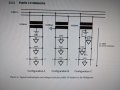
What configuration do you have A or C? Most Metro Manila connections are A.
IMG_20200807_190543.jpg
https://www.doe.gov.ph/sites/defaul...nual-for-interconnection-of-rooftop-pv-v5.pdf

3.2.1 Public LV-Networks
Most LV networks of Meralco and PEPOA-DUs are according to Configuration A of Figure 2. This type of system corresponds to an American “split-phase” network, but with the exception that the neutral conductor does not extend to the load. Therefore, both conductors of a Configuration A – LV network represent a phase conductor, which is quite unique. Electric Cooperatives predominantly use Configuration B. Here, one of the two conductors is earthed at the transformer side. As in case of Configuration A, the load voltage is equal to 230V but with one conductor being a phase conductor and the other conductor being a neutral conductor. This system corresponds to European standards. Configuration C finally represents a classical 3-wire split phase connection, where both voltage levels, 230V and 115V, are available. As shown for Configuration C in Figure 2, it is possible that the neutral conductor of a LV feeder does not extend to the end of the feeder so that the end point may finally correspond to Configuration A
We had type B at our location in the province of Zambales. These is why we derived our own in-home residential split-phase distribution using transformers.
 
Last edited:

Thread Starter

the_uglydog

Joined Aug 5, 2020
12
Hi All! We've been checking everything and found some splices inside the conduits as well as the ones we saw exposed. (the nitwits doing the wiring must have cut the wires too short when installing) We redid those and redid the splices at the drops and it works perfect. I'm planning on ordering some Morris insulated splice connectors from Amazon to redo all the connections from the meter throughout the property. Would that be a good choice? Nothing like that is available here but stuff from Amazon arrives in about 3 days.
 

MisterBill2

Joined Jan 23, 2018
27,980
It was clear that the problem was a bit of resistance some place, but I had not considered that there would be splices inside conduits. Hidden poor splices is an unexpected way to cause problems.
Unfortunately I am not familiar with Morris Insulated splices and so I can't comment on that.
 

jpanhalt

Joined Jan 18, 2008
11,087
Hi All! We've been checking everything and found some splices inside the conduits as well as the ones we saw exposed. (the nitwits doing the wiring must have cut the wires too short when installing) We redid those and redid the splices at the drops and it works perfect. I'm planning on ordering some Morris insulated splice connectors from Amazon to redo all the connections from the meter throughout the property. Would that be a good choice? Nothing like that is available here but stuff from Amazon arrives in about 3 days.
Splices inside conduits are not allowed in the NEC code. Do you mean that you replaced those splices with continuous wire runs?

As for the Morris splices, I suspect they are OK inside a box or fixture of sufficient volume. Given your heat and humidity, are insulated wire nuts available? Properly twisted wires, a good wire nut, and then wrapped with electrical tape is pretty secure. That method is used for commercial wiring in the US. I always put the tape on in the direction such that its tension would act to tighten the wire nut.
 

shortbus

Joined Sep 30, 2009
10,049
That method is used for commercial wiring in the US. I always put the tape on in the direction such that its tension would act to tighten the wire nut.
That, the tape is no longer up to the NEC code. My oldest grandson just went through his apprenticeship a couple of years ago, and told me that NEC now says that isn't code proper. Wire nuts OK but no tape.
 

jpanhalt

Joined Jan 18, 2008
11,087
That, the tape is no longer up to the NEC code. My oldest grandson just went through his apprenticeship a couple of years ago, and told me that NEC now says that isn't code proper. Wire nuts OK but no tape.
Interesting. Is flame retardant tape prohibited or just not required/recommended.
 

Lo_volt

Joined Apr 3, 2014
373
When using wire nuts, it's important to pull on EVERY wire inside it to ensure that all of them are gripped inside the wire nut. This is especially important with large numbers of wires. I've seen situations where all the wires were in the wire nut, but one or more was loose. That can cause issues such as what the OP is seeing or worse, it can cause overheating.
That, the tape is no longer up to the NEC code. My oldest grandson just went through his apprenticeship a couple of years ago, and told me that NEC now says that isn't code proper. Wire nuts OK but no tape.
I'm not fond of wrapping things in electrical tape. All it does is give a false sense of security and leave black sticky goo on everything.
 

jpanhalt

Joined Jan 18, 2008
11,087
When using wire nuts, it's important to pull on EVERY wire inside it to ensure that all of them are gripped inside the wire nut. This is especially important with large numbers of wires. I've seen situations where all the wires were in the wire nut, but one or more was loose. That can cause issues such as what the OP is seeing or worse, it can cause overheating.

I'm not fond of wrapping things in electrical tape. All it does is give a false sense of security and leave black sticky goo on everything.
The test for loose wires is best done before attaching the wire nut. That is, the mechanical twisting should give a secure joint before using the wire nut. The wire nut is simply to keep them that way.

As for goo, I agree some electrical tapes do that, but not all. The tape I use does not leave goo. Self-fusing tape doesn't leave goo either, but it is a PITA to remove if for some reason you need to do that.
 

shortbus

Joined Sep 30, 2009
10,049
Interesting. Is flame retardant tape prohibited or just not required/recommended.
Next time I see him I'll ask. I grew up wrapping them and when he saw me doing it he said if it was inspected it wasn't up to latest code. Those code books are too expensive for me to buy one.
 
Top