Facebook
 Google
 GitHub
 Linkedin
Hey guys
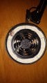
I’m having a problem with a fume extractor I bought in that it experiences a voltage drop at full power. It’s a 5V USB fume extractor with lights and a control unit for motor on/off, lights (shades and brightness). However, when the lights are on full and the fan is on the fan slows down, NOT the lights only the fan, lights seem unaffected either way). Lights still cause a voltage drop of 0.5V when operating alone but it appears unnoticeable. I’ve tried opening the control unit and using a direct 5VDC 20A ATX supply and the drop still happens. If I lower the brightness the fan speed with increase again, so something is a bottleneck. I had assumed the USB cable was too high a resistance but apparently not as I’ve gone right to the board to supply it now.
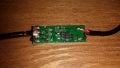
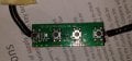
Looking at the control board I think they all share a common positive and have switched grounds. But I am a little confused about it. I am thinking either
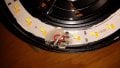
The LEDs draw approximately 1.6A and the fan 0.4A. The cable for the common supply looks to be 24AWG.
Anyone got any ideas on this? I got a half refund from the seller so I could hack at it but I’m not entirely sure what’s at fault at the moment. To make matter worse I cannot make sense of the IC they used and how it controls brightness and all 3 FET gates. It’s Vcc pin looks like it’s a potential divider.
As always, any and all help is appreciated.
Thanks in advance")
TLDR Voltage drops when lights used in fume extractor/light unit. Doesn’t appear to be wiring as a jumped the common with a thicker wire, no change.
I’m having a problem with a fume extractor I bought in that it experiences a voltage drop at full power. It’s a 5V USB fume extractor with lights and a control unit for motor on/off, lights (shades and brightness). However, when the lights are on full and the fan is on the fan slows down, NOT the lights only the fan, lights seem unaffected either way). Lights still cause a voltage drop of 0.5V when operating alone but it appears unnoticeable. I’ve tried opening the control unit and using a direct 5VDC 20A ATX supply and the drop still happens. If I lower the brightness the fan speed with increase again, so something is a bottleneck. I had assumed the USB cable was too high a resistance but apparently not as I’ve gone right to the board to supply it now.
Looking at the control board I think they all share a common positive and have switched grounds. But I am a little confused about it. I am thinking either
- The board IC limiting current (not sure why only the motor though)
- Transistors are limiting (but why not all the time?)
- The common supply wire is too thin and there is too high a voltage drop at 2A.
- Something I know not of.
The LEDs draw approximately 1.6A and the fan 0.4A. The cable for the common supply looks to be 24AWG.
Anyone got any ideas on this? I got a half refund from the seller so I could hack at it but I’m not entirely sure what’s at fault at the moment. To make matter worse I cannot make sense of the IC they used and how it controls brightness and all 3 FET gates. It’s Vcc pin looks like it’s a potential divider.
As always, any and all help is appreciated.
Thanks in advance
TLDR Voltage drops when lights used in fume extractor/light unit. Doesn’t appear to be wiring as a jumped the common with a thicker wire, no change.
Attachments
-
 859.7 KB Views: 17
 -
 649.8 KB Views: 17
 -
 757.5 KB Views: 17
 -
 322.8 KB Views: 16