voltage drop in bipolar power supply ±5v

Thread Starter

siavosh1

Joined Apr 16, 2019
20
Hi everybody
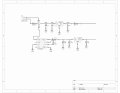
I designed this bipolar power supply that can supply +5 and -5 volts to the circuit. The positive pole gives +5v correctly, and there is no problem when connecting the load, but when the load is connected to the negative pole of the circuit, we face a voltage drop. Although I expected the negative pole to be able to conduct current up to about 200 mA, but with 30 mA, the voltage dropped from -5v to -3.8v.
This circuit is composed of 3 circuits (according to datasheets).
Vbattery = 7.4v (2 cell lipo)
How knows what is wrong?
Thank you for your answers.
 

Attachments

crutschow

Joined Mar 14, 2008
34,285
This circuit is composed of 3 circuits (according to datasheets).
Vbattery = 7.4v (2 cell lipo)
How knows what is wrong?
You said "according to the datasheets" but apparently you did not read them.
You read the data sheets of the ICs to determine their current output rating, just like we do to answer your question. :rolleyes:
 

sagor

Joined Mar 10, 2019
903
With LV connected to ground, expected input supply voltage is less than 3.5V. If feeding 7.4V, LV should be left floating (Microchip TC7660 datasheet, paragraph 3.5)
 

Thread Starter

siavosh1

Joined Apr 16, 2019
20

Thread Starter

siavosh1

Joined Apr 16, 2019
20
hi sia1,
Which type of IA requires a +/-200mA supply.?
E

Look here:
https://www.ebay.co.uk/sch/i.html?_...kw=positive+to+negative+DC+converter&_sacat=0
hi ericgibbs,
Actually, in this IA, we have a part for reducing the ripple in the signal because our signal maybe have 80uv, and the ripple can make a problem for us. The Source of this ripple is the power supply. To solve this problem, we give a sample from the original signal, reverse it, and then sum the ripple of these signals (original + reverse). Because of this design, we need ±5v to supply the opAmps.
 

ericgibbs

Joined Jan 29, 2010
18,766
hi sia,
I understand the requirement for a dual power supply when using certain types of IA's.
The requirement of +/-200mA sounds a high current for an IA.

What is the IA type/number.?

E
 

ericgibbs

Joined Jan 29, 2010
18,766
hi sia,
Thanks for the circuit diagram.
I can see it is a bigger project than just a single IA.

The problem with switching power supplies is the radiated and supply line electrical noise levels, especially when you are amplifying signal levels of 80uV,

My option would be a second battery pack for the negative supply, use low voltage drop regulators for the plus and minus 5V supplies.

E
 

Thread Starter

siavosh1

Joined Apr 16, 2019
20
hi sia,
Thanks for the circuit diagram.
I can see it is a bigger project than just a single IA.

The problem with switching power supplies is the radiated and supply line electrical noise levels, especially when you are amplifying signal levels of 80uV,

My option would be a second battery pack for the negative supply, use low voltage drop regulators for the plus and minus 5V supplies.

E
I appreciate your help so much. Due to the limited space in the used box, I wanted to use a 2-cell battery and supply both positive and negative voltages from this battery through the voltage reversing circuit, but I think I have to re-design in the same way as you said. (4 cell lipo with ±7.4)
 

ericgibbs

Joined Jan 29, 2010
18,766
hi,
The advantage of using 4 cells will double the running time of the project before recharge.
Also, the electrical noise problem will be avoided.

Good Luck with the project.

E
I expect a double helping of BAKLAVA .;)
 
Top