Voltage Comparator - verifying two incoming signals (voltage) are the same value

Thread Starter

QuantumElectro

Joined Jun 19, 2019
15
Hello,

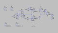
I was assigned a project to design a circuit that verifies that two incoming signals (voltage) are of the same value. Does anyone have any advice on how they would approach this design? Maybe just components to start with.

I saw that the LM2903 Dual Voltage Comparator can compare signals of the same value.

Thank you.
 

AlbertHall

Joined Jun 4, 2014
12,345
Because they are analogue voltages, you cannot verify that they are equal (because they never will be exactly equal) only that they are within some tolerance of each other - within 1mV say. So how near to each other do they have to be to be called 'equal'?
 

Thread Starter

QuantumElectro

Joined Jun 19, 2019
15
Okay. I can do the 1mV method. I don't think I could use the LM2903 dual voltage comparator because the signal voltage could be anywhere from 5-11.5v and I do not want to have a voltage range on the comparator.

How would I setup a the circuit to take two input voltages and determine if they are 1-10 mV from each other? Any certain components I should look into?
 

Thread Starter

QuantumElectro

Joined Jun 19, 2019
15
Look for the concept of window comparator.
After conducting research, I do not think this would work.

I need to be able to input 2 different voltages and determine if they are the same (+-10mV)

These input voltages could vary from 5-11.5v. While the Window Comparator does allow for the upper and lower limit for voltages, it does not offer some sort of similarity comparison, or difference measurement between the two circuits.
 

AlbertHall

Joined Jun 4, 2014
12,345
See how you migh
After conducting research, I do not think this would work.

I need to be able to input 2 different voltages and determine if they are the same (+-10mV)

These input voltages could vary from 5-11.5v. While the Window Comparator does allow for the upper and lower limit for voltages, it does not offer some sort of similarity comparison, or difference measurement between the two circuits.
Don't dismiss it so easily.
 

danadak

Joined Mar 10, 2018
4,057
You can do it with an ATTINY85 or Arduino and a little code.

Just use 2 analog inputs, compare the output of the results to be within some acceptable error.

Use mBlock to do the coding. Project attached, unzip it.

upload_2019-6-24_15-36-24.png


Regards, Dana.
 

Attachments

Last edited:

atferrari

Joined Jan 6, 2004
4,764
thank you! This helps.
After conducting research, I do not think this would work.

I need to be able to input 2 different voltages and determine if they are the same (+-10mV)

These input voltages could vary from 5-11.5v. While the Window Comparator does allow for the upper and lower limit for voltages, it does not offer some sort of similarity comparison, or difference measurement between the two circuits.
It all depends how you set the window's amplitude.
For example if extreme values of the window are LimitH= 3,30V and LimitL= 3,35V, once the other voltage is within the 50 mV window you could say they are "equal". Member @AlbertHall posted about that already.
 

atferrari

Joined Jan 6, 2004
4,764
BTW, some time ago, when designing a PID controller from scratch I used a window comparator where you can adjust not only the window level but the window width at will. It worked quite well.

Nice for playing to grasp the concept.

Will keep browsing my files to retrieve it for you.
 

Thread Starter

QuantumElectro

Joined Jun 19, 2019
15
BTW, some time ago, when designing a PID controller from scratch I used a window comparator where you can adjust not only the window level but the window width at will. It worked quite well.

Nice for playing to grasp the concept.

Will keep browsing my files to retrieve it for you.
Thank you. I will look into this method.
 

MrChips

Joined Oct 2, 2009
30,712
You don't need a window comparator.
Take the difference of the two voltages.
Feed that into a precision rectifier to convert it into a positive voltage.
Feed that into one input of the analog comparator.
Set the other input of the comparator to your threshold voltage, e.g. 10mV.

(You may have to scale everything upwards to get away from noise level.)
 

Zeeus

Joined Apr 17, 2019
616
Will this work? Maybe answers a little part of question

Inputs have to be the same frequency and not more than 10khz?...Using window Comparator as suggested

First op amp is difference amplifier, then if the output is within +-600mv then Window comparator output is high so LED D6 is turned on and stable

If difference of signals is greater than 600mv then from Windows comparator, the output will oscillate making LED D6 blink (not so high frequency )
 

Attachments

Zeeus

Joined Apr 17, 2019
616
You don't need a window comparator.
Take the difference of the two voltages.
Feed that into a precision rectifier to convert it into a positive voltage.
Feed that into one input of the analog comparator.
Set the other input of the comparator to your threshold voltage, e.g. 10mV.

(You may have to scale everything upwards to get away from noise level.)
yeah did this earlier but what if the voltages have different frequencies? output of doubler is high voltage

Please explain this "Feed that into a precision rectifier to convert it into a positive voltage."
Thanks
 

ericgibbs

Joined Jan 29, 2010
18,766
hola Agustin,
Ran your simulation LTSpice, looks fine.
As the TS has 5V thru 11.5V the 9V supply needs to be increased, say 12V to 15V. [or his inputs divided down]
I have used a lower test Va,hola_cap1.PNG Vb
Eric
 

Attachments

Top