Voltage/Capacitors 8.48

Thread Starter

mattcalder

Joined Mar 5, 2017
4
8-48.jpeg 
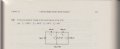
So I am new here and brand new to the subject and I was hoping for some help. I can get the Voltage across V1 by calculating the total capacitance of the caps and multiplying it by the voltage source to get the total charge, then dividing it into cap 1, but getting the voltages across the remaining caps escapes me. Please excuse my lack of knowledge, again, I am brand new to the subject. Any help would be greatly appreciated.
 

Attachments

dl324

Joined Mar 30, 2015
16,846
Welcome to AAC!

More readable image:
upload_2017-3-5_9-52-57.png

If you weren't given any of the voltages (i.e. answers), how would you calculate the voltage across C1 (V1) and C2 (V2)? Once you know V2, calculating V3 and V4 is the same process.
 
Last edited:

shteii01

Joined Feb 19, 2010
4,644
You have capacitors in series and capacitors in parallel. Do you know how to find equivalent capacitance of two capacitors in parallel? Do you know how to find equivalent capacitance of two capacitors in series? Can you find equivalent capacitance of the whole circuit and then work backwards and applying voltage divider principal in the process?

Haven't you done the same with resistors already?
 

Thread Starter

mattcalder

Joined Mar 5, 2017
4
Thank you all for your help and clues to this problem. It is very much appreciated. I realize I should have been more clear in where I'm at and what I know at this point in regards to circuitry.

So I know the equivalent capacitance of two capacitors in series and in parallel. If I am correct, let C1 and C2 be two capacitors. If they are in parallel, I add the capacitance values. If they are in series, I use the formula (1/C1 + 1/C2)^-1, the same formula for resistors in parallel (1/R1 + 1/R2)^-1. So what I've done so far is calculate the equivalent capacitance for the whole circuit of capacitors. This is what I've done. Let V1=C1 (300pF), V2=C2 (120pF), and so on:
C3 is in series with C4 which is equal to 480pF. C3 and C4 are parallel with C2 so that becomes 600pF. Finally, C1 is in series with 600pF so the total capacitance is 200pF. From there, I've calculated the charge using Q=CV, (200pF * 300V = 60nCoulombs). After that, to get the voltage across C1, I used the charge divided by the C1: 60nC / 300pF = 200V. Now from here this is where I am getting hung up. So am I correct in using the KVL to say the voltage across C2 is 300V - 200V = 100V? And from there, to find the remaining voltages across C3 and C4, do I use the voltage divider formula? Or am I to calculate the charges on each capacitor first, then divide it again by each capacitance?

Thank you again fro your help. I hope you'll forgive my ignorance on this subject.upload_2017-3-5_9-52-57.png
 

WBahn

Joined Mar 31, 2012
29,979
You have made a lot of progress.

Yes, KVL tells you that V2 is 300 V - 200 V = 100 V.

There are a few ways to go from here. First, since you know that there is 100 V on C2, can you find the charge on C2? If so, then you know that charge had to come from the 60 nC of charge that was pushed out of the negative plate of C1. So where did the rest have to go?

Another way is to ignore everything except C3 and C4 and say that, somehow someway, 100 V got placed across the series combination of them. Then the exact same process you used to find the charge of C1 and the voltage across it would apply.

It's worth noting that the problem is requiring you to make an assumption in order to calculate anything -- namely that all of the capacitors were initially uncharged and that all of the charge distribution is due to the 300 V source. If any of the capacitors were initially charged when the circuit was built, the results will be significantly different. In general, this assumption of zero initial charge is not a good one -- it is trivially easy to build a circuit in which this assumption will yield incorrect results. But in a problem like this you just don't have much choice. But you should state that you are operating under this assumption.
 

MrChips

Joined Oct 2, 2009
30,720
Whoa!

Who is teaching this course?

Which textbook is this?

Connect two capacitors in series. What is the voltage across either capacitor?

@WBahn, I acknowledge that you recognize the problem and has stated the conditions.
The other real world problem is you can hardly validate this experimentally with real world capacitors and voltmeters.
 

WBahn

Joined Mar 31, 2012
29,979
You can come very close. Low leakage capacitors and most modern DMMs will let you make measurements that are quite close to the nominal values for a sufficient amount of time to valid the theory. Watching the values change away from the expected values with time is, by itself, a worthwhile learning experience. In addition, many real world circuits rely on these principles for how they operate -- a common example is sampling circuits, particularly in ICs. Switched-capacitor filters are another example. A key design parameter in all of these circuits is how long the capacitors can be expected to retain their charge sufficiently well for the purpose at hand. For some circuits that limit is microseconds, while for others it is minutes or even hours. I don't know what the longest practical time is, but would not be too surprised to discover it is measured in weeks or longer.

But, as an academic exercise, this problem is at the level of introductory physics problems before the notion of friction is introduced. It's aim is to get across core concepts and, once those are in place well enough, more realistic models can be introduced and worked with.
 

MrChips

Joined Oct 2, 2009
30,720
You can come very close. Low leakage capacitors and most modern DMMs will let you make measurements that are quite close to the nominal values for a sufficient amount of time to valid the theory. Watching the values change away from the expected values with time is, by itself, a worthwhile learning experience. In addition, many real world circuits rely on these principles for how they operate -- a common example is sampling circuits, particularly in ICs. Switched-capacitor filters are another example. A key design parameter in all of these circuits is how long the capacitors can be expected to retain their charge sufficiently well for the purpose at hand. For some circuits that limit is microseconds, while for others it is minutes or even hours. I don't know what the longest practical time is, but would not be too surprised to discover it is measured in weeks or longer.

But, as an academic exercise, this problem is at the level of introductory physics problems before the notion of friction is introduced. It's aim is to get across core concepts and, once those are in place well enough, more realistic models can be introduced and worked with.
Accepted. But note that the values in this assignment range from 120pF to 1200pF.
You would not get any meaningful results trying to measure voltages with a DVM with 10MΩ impedance.
At the very least, one need to test this with >100nF values and electrostatic voltmeters (if you can find one).
 

WBahn

Joined Mar 31, 2012
29,979
Accepted. But note that the values in this assignment range from 120pF to 1200pF.
You would not get any meaningful results trying to measure voltages with a DVM with 10MΩ impedance.
At the very least, one need to test this with >100nF values and electrostatic voltmeters (if you can find one).
Agreed.

Though it really drives home how high impedance CMOS IC circuits are when sampling capacitors that hold their charge for significant amounts of time are often measured in femtofarads.
 

MrAl

Joined Jun 17, 2014
11,396
Hello,

This problem seems to be presented in a very improper way. That is because the source should be an AC source not a DC source. There are a couple reasons for this.

One that stands right out is that an ideal DC source placed across an ideal capacitor(s) creates an infinite current.

Given that the above is still allowed, then treat the DC source as an AC source and go on to calculate the transfer function from input to across one of the caps and the result shoots right out. You can think of the DC source as a step change if you like, but the result will come out the same after the transformation back to the time domain. All the impedances turn into one simple dimensionless ratio which of course is then again independent of frequency.

We run into this situation once in a while in real life, where capacitors are being used to force a certain response amplitude near t=0 where normally we might have to wait several time constants to get that 'initial' amplitude. Of course it could cause the power supply to fail to start up if the caps are too big.
 
Last edited:

WBahn

Joined Mar 31, 2012
29,979
Come on! Look at the level of the problem -- does it really look like a problem given to someone that is going to have the faintest clue about transfer functions and time constants and step inputs and transformations between the frequency and time domain? The audience for this problem very likely has not even been formally introduced to the notion of DC and AC. Their world likely has consisted of batteries and resistors up to this point and now they are just being introduced to capacitors and how they combine and how they share charge.
 

Thread Starter

mattcalder

Joined Mar 5, 2017
4
You have made a lot of progress.

Yes, KVL tells you that V2 is 300 V - 200 V = 100 V.

There are a few ways to go from here. First, since you know that there is 100 V on C2, can you find the charge on C2? If so, then you know that charge had to come from the 60 nC of charge that was pushed out of the negative plate of C1. So where did the rest have to go?.
WBahn,

First off, thank you for your patience with me. Being so very new to this can be frustrating and discouraging and make one want to give up, but your help and kindness, taking into account my low level of education on this subject, is very encouraging and motivates me to go onward.

So I think I understand now, at least in the context of this problem, now realizing there is much I do not understand about a circuit like this in the real world:

100v to C2 would equal 12nC of charge for C2. From there, series capacitors C3 and C4 have a voltage of 100v across them together and their combined capacitance (800pF in series with 1200pF) is 480pF. This means the charge would be 480pF x 100v = 48nC. This charge for C3 and C4 would be then calculated into each respective capacitor. This comes out to be 48nC/1200pF = 40v, and 48nC/800pF = 60v.

Please feel free to correct me or supplement me with any information I may have mistaken or not taken into account, and again, thank you all very much for the help.
 

WBahn

Joined Mar 31, 2012
29,979
Very good. The only thing I see worth pointing out is a slightly different approach (but yours is perfectly valid) that could either be used to get the solution or to act as a sanity check on your results.

You had 60 nC that was pushed through the first capacitor. You then calculated 12 nC on C2. That means that the rest, 48 nC, had to flow into C3 (and also C4). This matches what you calculated and so serves as that sanity check. But notice that we found how much charge was on each capacitor without having to find the effective total capacitance. So once we know that each cap has 48 nC of charge we can find the voltages directly.

Yet another approach, once we have the 100 V across C2 (and, hence, across C3+C4) is we can use the voltage divider rule for capacitors, which in this case gives us the voltage across C3 as

Vc3 = 100 V * (C4/(C3+C4)) = 100 V * (800 pF / 2000 pF) = 40 V

If you haven't already, I'd recommend deriving this voltage divider rule for capacitors for yourself.
 
Top