Visually identify the primary side of a 120 V transformer?

Thread Starter

Tonyr1084

Joined Sep 24, 2015
9,744
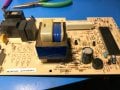
I have a circuit board out of an old microwave oven, complete with the keypad and the display. Notwithstanding, I'm considering using it for some sort of timing function - to be defined at a later date. For now I want to know how to identify the 120 VAC IN side of the transformer. It's likely a step-down transformer and personally I don't care what the secondary voltage is. Whatever it is it's what the circuitry needs to operate. I can just use the relay output as a timed switch, or I can use the countdown feature with an alarm (beep) at the end of the countdown.

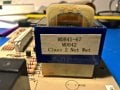
Looking at the transformer, underneath the tape covering the windings (and it's not going to be easy to strip away the tape) it looks like the secondary side is a larger gauge wire than the primary side. Of course I'm guessing, and guessing can be a bad thing if you apply the wrong voltage to the wrong side. Since the transformer is "In Circuit" and I don't feel like isolating the secondary side (if what I think is the secondary), taking a resistance reading isn't going to yield any real useful information that I can think of.

So, just by visually observing what appears to be one side of large gauge wire versus the other side of much finer wire - am I right to assume that a step down transformer would have the fine wiring on the primary side?
 

MaxHeadRoom

Joined Jul 18, 2013
30,771
Can you identify which winding is the first wound, (closest to the core) if so this is usually the primary.
If it is step down, typically the secondary will be the larger gauge of the two.
Cannot you do some reverse engineering of the board that may confirm it?
Max.
 

AlbertHall

Joined Jun 4, 2014
12,640
Your ohmmeter could be used to figure out which winding is connected to a rectifier and which winding is connected to mains input.
 

Thread Starter

Tonyr1084

Joined Sep 24, 2015
9,744
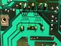
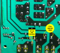
From what it appears, P9 (at the bottom) would be the Line and P12 & P13 would be neutral. P11 & P18 would be electronically switched on by the transistor. The capacitor (175v, 395-BC) appears to be across the lines in.

The transformer appears to be a dual secondary output with a center tapped secondary. Again, I'm not concerned with what the transformer is doing, I just want to hook this up to 120 V and see if I can make it do something for me.

image1.jpg image2-2.png
 

Dodgydave

Joined Jun 22, 2012
11,395
I would say the two single windings in series are the Primary, and the centre tapped is the Secondary, the Bt139 is a Triac controlling terminals P11/18 mains for something else.
 

MaxHeadRoom

Joined Jul 18, 2013
30,771
The 595-BC appears to be the Varistor shown in the front view, if so and those are spade terminals below it, then those two are most likely the power in.
Max.
 

Thread Starter

Tonyr1084

Joined Sep 24, 2015
9,744
For those interested: P9 (hot), P12 (or P13) (neutral), P11 (or P18) is controlled by the fan button. Either high or low or off. Can also control an incandescent light (high, low, off). When I run the "Cook" cycle I can hear a relay kicking in and out several times then stop. Goes like that for about 2 seconds. Don't know what it's looking for. IF I "Cook" on ZERO power the relay is silent. There are a few other relays on the board I haven't figured out what they do yet. But the clock works. I have yet to find the light circuit. There is another connector (spade lug) (P8) that upon power-up it has 2 volts AC present with no load. When I push the light button on the panel it goes hot (120 VAC, first push, 66 VAC second push). So the light has two level settings as well. Unfortunately I haven't found the point where when the {oven} is on I have power. Still trying to figure that one out.

There IS a large relay with two spade lugs on top. I get no power there at all no matter how I configure things. When I connect my meter across both lugs and set to ohms I get an indication of intermittent connection (zero ohms) but because it's clicking rapidly my digital meter never gets a chance to settle down on any specific reading.

There is a green plug with four wires. Two I cut a long time ago when I was scrapping the oven and two still have their spade lugs on them. I'm assuming they are sensor wires for thermal switches, so I've jumped them together in the ordered pairs they appear to be but the relay is still clicking for five seconds then it stops. This may be the very reason why the oven was being thrown out in the first place - not knowing is a hamper to progress. Nevertheless, I do have something that can control small loads such as a fan or a light. Beyond that I don't know how much current (or wattage or VA) I can carry through those two circuits I HAVE identified. On top of that I don't even know what brand or model this control panel is from. At best there's a label that says "MCMS1(04) 4619-64028641". I'll google that and see what comes up.

Nope! No luck. Got all kinds of stuff. Even when I put the word Microwave before the label I still get nothing solid. Just microwave stuff.

[edit] Just connected a battery and LED to the relay in question. Definitely it's the one that is clicking in and out. The LED is flashing with the relay clicking.
 
Last edited:

Thread Starter

Tonyr1084

Joined Sep 24, 2015
9,744
Here's the relay in question:

https://media.digikey.com/pdf/Data Sheets/Omron PDFs/G5J.pdf

Pins 1, 3 & 4 are PCB soldered. Pin 1 also appears above the relay as a spade lug, as does pin 2 as well. When the relay kicks in the contact between pin 1 & 2 closes. Since the relay doesn't stay clicked in I can't decide if the relay is faulty or if there's another component on the board causing this problem. The relay clicks for 4 seconds if you set the oven to cook for longer than that. I'll see if I can shoot a video.
 

MaxHeadRoom

Joined Jul 18, 2013
30,771
It may not help in this case, but of the major appliances that I have repaired that involve power switching, high wattage elements etc, the relays used are in some cases so puny I am suprised they have lasted thus far.
One problem is the pins are so puny that the surface contact area with the PCT board is so minimal and usually blow a pin off.
The one you show looks quite a bit heavier.
Max.
 

Thread Starter

Tonyr1084

Joined Sep 24, 2015
9,744
Yeah Max. Was trying to avoid pulling the board out of the housing again. But I guess one must do what one must do.

Just concluded another test. Set the oven to cook for one minute at a power level of one, five and seven. After 28 seconds the relay clicks again; regardless of the power setting. The ONLY setting where it doesn't do any clicking is at zero. But alas, I guess I'll go ahead and test the board for coil voltage. With it clicking as fast as it is I may have to set up the scope. But not until I know the working voltage of the relay. It SHOULD be 24 volts. I wonder if something in the circuit is trying to push that voltage but failing and shutting down for 28 seconds then it tries again.

Regardless of the settings (except for zero) every approx 28 seconds it cycles for four seconds.
 
Top