Vintage single phase motor wiring

Thread Starter

AndrewSB

Joined Oct 29, 2020
9
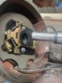
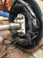
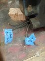
I have an old single phase 1/2hp 110v capacitor start motor that came with my clausing 4800 lathe, the motor has 4 wires sticking out, no capacitor and came with a switch with a ton of connection points, i have identified one of the winding which I assume is the run since the resistance is fairly low but i am lost as how yo wire this sucker and what size capacitor I need. A1 and A2 have 1.4 ohms on the 200 ohm setting, the centrifugal switch wire is obviously the one coming off the switch, the unlabeled wire is a mystery, its got around 1 million ohms to the centrifugal switch wire when the centrifugal switch is closed, and is infinite otherwise, and this big switch makes no sense, its labeled as a 1ho switch which probably isnt a problem, it has only the line and neutral wire and no ground
 

Attachments

MaxHeadRoom

Joined Jul 18, 2013
28,686
Unusual to see a 1/2 HP motor with a CF switch.
But if you have two windings and have identified the resistance of each, as you assumed. the low one should be the run winding.
The start in series with a ~5uf - 10uf motor start cap and the start switch, it should show zero resistance when closed of course, run some 400 emery through it if it shows open.
If you just power it up using only the start winding and spin the shaft at the same time, it will usually take off and run, direction doesn't matter.
 

Thread Starter

AndrewSB

Joined Oct 29, 2020
9
Im not familiar with this type of switch, I also dont have a capacitor on hand, how would I test this sucker out, also for the power cord going in, what would I do with the ground?
I am thoroughly confused on how to hook of the power cord coming in, I was going to look at how my 2 old bench grinders are wired but they both only have 3 wires coming from the motor
 

Thread Starter

AndrewSB

Joined Oct 29, 2020
9
Could I just replace this switch for a more simple toggle switch like a single pole single throw or something similar
 

MaxHeadRoom

Joined Jul 18, 2013
28,686
Like I said, first try power to the run winding and give the shaft a spin at the same time.
The ground lead goes to the frame of the motor.
 

Thread Starter

AndrewSB

Joined Oct 29, 2020
9
Hooked it up how you said and it did just that, hummed when plugged in and them gave it a spin and it picked right up, used the motor like that for a little while but I'd like to just flip a switch and it to turn on, still very confused on how to wire this guy, and more importantly what size capacitor to use, I pulled a 189-227 uf 120v cap from one of my bench grinders, dont know if this is to big or not, the bench grinder is a 3/4 hp. I have identified the run winding obviously and i know that one of the other wires comes from the centrifugal switch, the 4th and final wire goes off into the motor and only has continuity to the wire coming from the centrifugal switch when it is depressed, however its a little over 100k ohms. then of course you have your line coming in, ground to motor, and then neutral and power.
 

MaxHeadRoom

Joined Jul 18, 2013
28,686
Rather unusual to have a centrifugal SW on such a small motor, if you can identify the start (high resistance) winding, use a 100uf motor start capacitor rated version.
Ensure the start switch is made initially when stationary.
The low resistance winding should be in circuit the whole time (across the supply).
 

MisterBill2

Joined Jan 23, 2018
18,491
Lots of motors had and have start switches, and most of those did not use a capacitor, but rather the higher resistance of the start winding to create the phase shift. And that 3 pole switch is for reversing rotation.
 
Top