Variable PSU not producing wanted results

Thread Starter

ChickenMcDo

Joined Jun 4, 2022
1
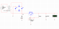
Would like to ask help why my circuit is not working? In the first one, the capacitor is exploding and it produces very small results. For the second one, the capacitor also explodes and doesn't produce the needed results.

The needed results are from 0 to 12 volts. Both use a 12V, 1A transformer. 1654364044298.png1654364031100.png
 

Attachments

k1ng 1337

Joined Sep 11, 2020
960
In the first schematic there is a short circuit from the D2 / D3 / C1 node to the transformer. In the second schematic there is another short circuit from the D3 / D4 node to ground.

Fullwave-Bridge-Rectifier.png

Edit: Is C1 in the second schematic a wire or capacitor? It has the name but looks like a wire. R3 is connected to ground on both sides and there is a seemingly misplaced node nearby.
 
Last edited:

dl324

Joined Mar 30, 2015
16,916
Welcome to AAC!
In the first one, the capacitor is exploding and it produces very small results.
The bridge rectifier and capacitor connections are wrong.
the second one, the capacitor also explodes and doesn't produce the needed results.
Schematic is too messy. Will analyze later (maybe).

Are things blowing up in the simulator?

Next time, print to PDF and take a clip so we don't have to deal with the grid or meaningless colors.
 

KeithWalker

Joined Jul 10, 2017
3,091
The layout of your circuit diagram makes it very difficult to follow. Have a look on-line at how other linear regulated power supply circuits are drawn and try to simplify yours..
What is the voltage rating of the capacitor? When the circuit is wired correctly there will be approximately 16V across it, It should be rated for at least 25VDC,
 
Last edited:
Top