 Facebook
 Google
 GitHub
 Linkedin
Hello , Am wondering if anybody can help me please. I have been looking for a (ideally) AC/DC variable power supply but not too expensive ,
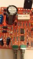
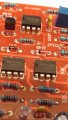
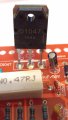
Ideally for 0 volts to about 35 volts after looking around my head was spinning with all the different types but i stumbled across a DC 0-30 volt kit to build (which looks straight forward to build) on ebay
http://www.ebay.co.uk/itm/Regulated...V-2mA-3A-Precision-Variable-Lab-/132104143924
so with it been cheap and thought it i would get me half way to my goal ..
Problem i have is that after i assembled it, and checked it , its not working , i got 20 vac going in (it does say 24 vac tho but would this matter?) at the fan i get 24 volt but the output not power at all . could anyone give me any advice other that putting it in the bin . i have been i touch wit the seller but they don't know anything about electronics they just sell them (am guessing they buy them in from china or Hong Kong) they asked me to take it to a specialist to see if they can sort it , i will be getting back to them if i cant get it working to get a refund i just thought i would see if anyone has any experience with this type of power supply first .
Cheers Mal


")


