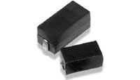
Using two resistors instead of one.

Thread Starter

danforth

Joined May 8, 2011
22
I need to use a 10W 1 Ohm resistor in a circuit. The problem is that the only kind that I can find are too big (ceramic wirewound through-hole).

My PCB is surface mount and I want to be as small and compact as possible. I am wondering if I can use two smaller surface mount resistors instead of the ceramic wirewound and if it will save me some space?

Also, is it better to wire two resistors in series or parallel when replacing a single resistor?

Thanks
 

kubeek

Joined Sep 20, 2005
5,796
If you need to dissipate 10W, then there is no helping you. Nothing in smd can dissipate 10W and be still soldered to the board.

I would say series because the connection is a little easier, but it doesn´t really matter.
 

beenthere

Joined Apr 20, 2004
15,819
Have you actually found 5 watt surface mount resistors? How big are the fins?

Consider mounting the resistor off the board, thus doing away with the space problem. If you need all 10 watts dissipated, use a larger resistor for reliability.
 

#12

Joined Nov 30, 2010
18,224
Of course (2) 5 watt resistors will dissipate 10 watts, but they will still be about the same size as a 10 watt resistor. It's like saying, I can't drink half a gallon of water, can I just drink two quarts?"
 

Thread Starter

danforth

Joined May 8, 2011
22

tracecom

Joined Apr 16, 2010
3,944
Does anybody know approximately how hot two 5W resistors would get? Would a heatsink be a good idea?
I am no expert at reading spec sheets, but it looks to me like these resistors could get to 220°C, which is hot enough to cause instant skin destruction.
 

#12

Joined Nov 30, 2010
18,224
I see the 220 C as the maximum allowable temperature, but I also see the derating graph showing 5 watts @ 25 C and ending at 0 watts and 280 C

It looks like "over 200 C operating temperature" but that's what I would expect from trying to use small resistors, a huge temperature penalty. If you don't want these running above 200 C, add cooling fins (suggested by beenthere).
 

ErnieM

Joined Apr 24, 2011
8,415
A heatsink is always advisable with a lot of power, but with SMD parts you are kinda limited to the pads it attaches to, which can be made large but the power is still in the board.

These parts are only rated at 5W at room temperature, so no going outside on a hot day.

There is no thermal resistance noted so no calculation of temperature rise can be made. The graphs do seem to indicate that at 5W the thing will get
to 220°C.

Series or parallel: Resistors typically fail open. With series if one part fails then the chain opens and the device dies. With parallel you get more resistance and some chance of some functionality.
 

SgtWookie

Joined Jul 17, 2007
22,230
10 Watts is 10 Watts, and you are going to have to get rid of the heat, or your board will be destroyed.

If you need it to be really compact, you might have to use water or mineral oil cooling. You might be able to use a heat pipe to transfer the heat elsewhere.
You might use forced air and fins for removing heat in a small space.

If you have more space, you can use forced air and copper pour areas for heat sinks.
If you have even more space, you can just use large copper pour areas and convection cooling by orienting the board vertically and providing access for air flow.
 

Adjuster

Joined Dec 26, 2010
2,148
To restrict the temperature rise, it might be advisable to use more than two 5W resistors (assuming that you can't get bigger ones), so that they operate well below their rated power. In surface-mounted construction, stresses due to differential expansion may limit the life of the product. Keeping to a more conservative rating will help to minimise this, as well as helping the reliability of the resistors themselves.

Whether or not doing this would be acceptable would of course depend on how significant the extra cost and bulk would be in your application.
 
Top