Not sure if it was mentioned, I did not read all the posts, but Frequency will give overall period, duty cycle carves up the period into 'on' and 'off' times. 'on' + 'off' must = period. So, with some simple math you can figure it out so things make sense.
a constant current source has an output that attempts to push a current that is constant as the load impedance varies from 0 to infinity. • • • Within the capabilities of the power supply, the voltage at the Q2 collector will do *anything* necessary to maintain 1.8 mA of collector current. Vcc is 6 V and the circuit needs a minimum of 1.2 V of operating headroom. Thus, as long as the voltage across the cap is between 0 V and 4.8 V, the charging curve of the capacitor voltage will be a straight line, not an exponential curve. Once the cap voltage reaches 4.8 V, it will sit there until something discharges it. Note that in the constant current situation there is no resistor in series with the capacitor. The charging current is controlled/limited only by the circuit.
I will calculate the values from the readings.
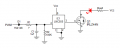
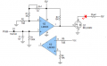
Construct this circuit first to get the voltage readings. View attachment 343465
EDIT: Corrected part # for D1
A whole lot of interesting electronic concepts have been presented, some fairly sophisticated ones with adjustments and calculations included. And while the actual signal is technically PWM, it is a rather complex scheme involving a lot of independent variables. And that signal is actually Pulse Length Modulation, with a whole string of independent pulse lengths encoded for independent variables. And the TS is not an expert:" I'm a noob in electronics and I need a schematic to turn LEDs ON or OFF using PWM signal in my RC car.
So I am suggesting a less sophisticated but much easier scheme, which is to get a low powered low speed (cheap) RC servo actuator and fit it with a lever to operate the light switch. I am guessing that a small, slow, and low powered RC SERVO will be much simpler and even less expensive than the purchased parts for the previous suggestions, if the TS does not have a collection of assorted electronic parts on hand. And probably a bit cheaper that the "AliExpress" item mentioned above.

 Facebook
 Google
 GitHub
 Linkedin