Facebook
 Google
 GitHub
 Linkedin

Here's a reference to the relay module.
Each relay is controlled by an opto-isolator input which is active low.
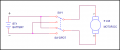
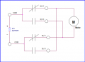
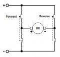
Below is a suggested circuit to operate two of the SPDT relays in a bridge configuration to control the motor.
A CD4013 flip-flop (2 in each package) provides the latch function.
R1C1 provides the mechanical switch debounce function by providing a short delay before the FF can be again triggered to change state.
R4C2 generates a power-on CLR signal so that both relays are unenergized and the motor is in the off state.
The pushbutton voltage is supplied from the opposite flip-flip /Q output to provide an interlock so only the appropriate pushbutton is active when the motor is ON.
The output of each MOSFET is connected to the respective relay control input on the board.
Each pushbutton turns the motor ON in one direction with a second push turning it off.
That way the motor doesn't instantly have to reverse direction, which can damage the motor.
So to change direction, you push one pushbutton (the one used to energize it) to turn the motor OFF, and then push the other push-button to start it in the reverse direction.
The diodes are to protect the relay contacts from any inductive transients from the motor.
The diode size depends upon the motor running current.
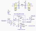
Each relay is controlled by an opto-isolator input which is active low.
Below is a suggested circuit to operate two of the SPDT relays in a bridge configuration to control the motor.
A CD4013 flip-flop (2 in each package) provides the latch function.
R1C1 provides the mechanical switch debounce function by providing a short delay before the FF can be again triggered to change state.
R4C2 generates a power-on CLR signal so that both relays are unenergized and the motor is in the off state.
The pushbutton voltage is supplied from the opposite flip-flip /Q output to provide an interlock so only the appropriate pushbutton is active when the motor is ON.
The output of each MOSFET is connected to the respective relay control input on the board.
Each pushbutton turns the motor ON in one direction with a second push turning it off.
That way the motor doesn't instantly have to reverse direction, which can damage the motor.
So to change direction, you push one pushbutton (the one used to energize it) to turn the motor OFF, and then push the other push-button to start it in the reverse direction.
The diodes are to protect the relay contacts from any inductive transients from the motor.
The diode size depends upon the motor running current.
Last edited: