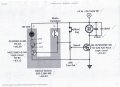
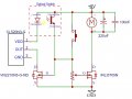
So simple. I love it. LowQCab, Les, and Reloadron thank you very much for your input and research into what looks to be a great solution. Even speed control! I will order parts asap and get this thing under way and post the result when it's finished.
BTW Reloadron I found some of Jmorris's posts and he fits the Fiddlers Class stereotype perfectly. He's given me more ideas.
Thanks again.
Andy
He is a really nice guy. I know he hangs out in The High Road forums and also Shooters Forum which is where I spend time also. Any problems or questions just catch any of us and let us know how that circuit plays out.
I have to confess, the Speed Control, while it does work,
is not suitable for use with a regular panel-mount Pot,
it's not linear, and has a big dead-spot in the first 3rd, and the last half of
the travel of the 20-Turn-Trim-Pot.
This is not an issue if the speed will just remain "fixed" after
a workable speed is established with the Trim-Pot.
A proper Panel-Mount-Pot with a Knob will require the addition of an Op-Amp.
The Trim-Pot must be between ~25K and ~50K so as
to not over-load the Photo-Transistor.
The Current-Regulator for the LED allows operation without a Voltage-Regulator,
as long as the peak-Power-Supply-Voltage does not exceed ~15-Volts.
The 2-FETs are extremely over-rated for the job they do.
No Heat-Sink will be required with a Motor that draws less than ~500ma,
larger-Loads will need a small Heat-Sink for insurance against over-heating.
All the part-numbers are from DigiKey,
where You can also download the various Data-Sheets.
.
.
.
I too like LowQCab's design particularly the clever way it latches. I was thinking of suggesting adding fixed resistor at both ends of the pot to utilise more of the travel of the pot. I then thought that if the mosfet was replaced with an NPN transistor and the motor moved to the emitter the transistor would act as an emitter follower so that the pot gave a linear voltage control to the motor. The problem with that idea is that the pot has to be a relatively high value to be driven from the phototransistor.
This would not provide a low enough source resistance to the base of the transistor. It might work if a darlington transistor was used. I think on balance an independent speed control part would be better.
I may have been sloppy and placed the part up-side-down,
I'd have to check the Data-Sheet again.
You should check the Data-Sheet to verify my work.
I make no guarantees of accuracy.
The CL520 / CL525 can be used as "floating" devices,
there is no Ground, but the Polarity must be correct.
.
.
.
If the function of CL520 is to stabilise the LED voltage then do we connect it like this, ignoring the GND? I've checked all the data sheets but some of it is beyond me. Please check if I'm on the right track. Thanks again.
Connect the "VDD" and "Out" Pins together,
then connect both of them to the Cathode (black-wire) of the InfraRed-LED.
"Ground" goes to the "Drain" Pin of the N-Channel MOSFET, ( or NFET ),
which switches the Ground-Connection for the LED On and Off.
( This is called switching the "Low-Side" of the Load, or, "a Low-Side-Switch",
as opposed to switching the "High-Side" of the Load.
Most people are more familiar with Switching the "High-Side" or "Hot" )
.
.
.
The CL520N3-G connections are wrong.
Pin 1 should go to +6 volts.
Pin 2 should go to the cathode of the IR LED in the opto switch.
Pin 3 should go to the drain of the VN2210N3-G-ND mosfet
The CL520N3-G does not stabilise the voltage to the IR LED. It stabilises the current through it to 20 mA.

 Facebook
 Google
 GitHub
 Linkedin


 Any problems or questions just catch any of us and let us know how that circuit plays out.