Use phototransistor and NPN transistor for motor control

Thread Starter

dncl

Joined Jan 3, 2014
5
Hi,
I'm doing my final project this sem, so now I try to use a phototransistor connected at the base at the transistor to control my 3v dc motor connected at collector of the same transistor.

So when there is no light, motor will move and stop when light hit phototransistor.

So I'm here to ask which NPN transistor is the best to use since the motor I use required high current (around 1A), or is that any idea to turn ON/OFF the motor?

I planned to follow the circuit at the link below:
http://www.evilmadscientist.com/2007/a-simple-and-cheap-dark-detecting-led-circuit/

Just change the resistor value and transistor and the load to a 3v dc motor.
Will it work? Any reply will be much helpful!
 

matty204359

Joined Apr 6, 2011
105
lithium coin cells have very high internal resistance. you prolly wouldn't get more than a hundred mA with a direct short. even if you could draw an ampere it wouldn't last very long at all. care to detail what this motor will be doing so I can help you choose a better battery?
 
Last edited:

Thread Starter

dncl

Joined Jan 3, 2014
5
Thx for reply and sorry for late reply,

Actually the motor I using is the motor build in in the train i brought from toy store, I plan to modify the train for my project so that when the train will stop automatically when it reaches station, it originally use 2 x 1.5 dry battery.

I plan to put the phototransistor underneath the train and insert LED under the track.
So it wont receive any light until when it's near station, once the LED light hit the phototransistor it will then stop the train.

I attach the picture of the train set that I brought over here.
1521466_10200450838548264_240807595_n.jpg
Sorry for bad English... :)
Will it works?
 

Dritech

Joined Sep 21, 2011
907
Hi,

It is best to use a micro switch instead of a phototransistor.

http://www.ebay.co.uk/itm/New-Micro...al_Components_Supplies_ET&hash=item4ac97a2ad6

Mount the switch under the train and connect it to the motor supply. When the train reaches the station, make the switch to close (using some kind to bump or something). The problem is that you have to move the train to deactivate the switch for it to work again else, the train will stay off. To eliminate this problem you have to use some kind of circuit, but I cannot help you since I don't know how your train actually works.

If you still want to use the phototransistor, you can use it in the same manner as the switch. There is no need to use an extra coin battery for it to work. You can use the batteries used to power the train.
 
Last edited:

tubeguy

Joined Nov 3, 2012
1,157
+1.
You could use a gentle ramp. Adjust so the train stops when switch roller is most of the way up the ramp.
Make the ramp movable vertically with the lower position completely flush or below the track ties.
Ramp raised to stop, lowered to start the train.

EDIT: Of course, the train car needs to be heavy enough to stay on the track when the microswitch is pushed up.
 
Last edited:

Alec_t

Joined Sep 17, 2013
15,163
Using a phototransistor presents problems. Even a slight amount of light will cause conduction. Have you considered how you would prevent daylight/room-light reaching the transistor via the space between train and track?
How will you control train deceleration? A sudden stop won't look natural.
 

Thread Starter

dncl

Joined Jan 3, 2014
5
Hi all,

Thx for the replies,
Micro switch is a good idea, I might consider it but it have to be deactivated by hand push which maybe will presents a problems. I have to find extra circuit to solve this problem.

@Alec_t Thx for your opinion, I thought about the problem you stated before, my opinion is to drill a holes underneath the train and put the phototransistor inside the train facing down the track to minimize the daylight effect, and since the space between the track and train quite small so I think it's okay (correct me if I'm wrong)

About the sudden stop, I still haven't figure out a good solution, and yeah it will look quite unnatural, any solutions u can suggest to solve this will be much appreciated.

Another question: Between LDR and phototransistor, which one is better?
And is there other solutions except micro switch and photo transistor? Can I use ir sensor for this application? Thx in advance. :)
 

Thread Starter

dncl

Joined Jan 3, 2014
5
Hi again,

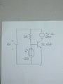
This is the circuit I try out today by connecting using a breadboard and it works quite well.
IMG_20140104_214449.jpg
If no light presents, the motor will keep moving and when the LDR get the light it will then stop the motor. But a small problem is that the light required to stop the motor have to be quite bright (about the brightness of flash light of a phone).
I wish to stop the motor with just the brightness of a red LED.
Will the problem solved if I increase the value of base resistance?
Or is there any other improvement I can make to the circuit?

Thx again in advance :)
 

Alec_t

Joined Sep 17, 2013
15,163
An LDR would be better IMO, because the change in current through it can be more pronounced for a given light level change.
IMO it would also be better to have a beam-break system, so that the light (or IR) source and sensor and all the electronics can be track-side instead of in the train. But that would require the train to be powered via the track. Is yours?
PWM could provide deceleration.

Will the problem solved if I increase the value of base resistance?
That would lower the light level needed to turn on the transistor, but would also reduce the motor current if the transistor was no longer saturated (turned on fully).
 

Dritech

Joined Sep 21, 2011
907
I would use a super bright white LED instead of a common red LED. The common red LEDs are not that bright and so the phototransistor will easily be triggered by ambient light it set to be triggered with such LED.

Also, in parallel with the motor include a flyback diode to protect the sensitive components from any back EMF created by the motor.

http://en.wikipedia.org/wiki/Flyback_diode
 
Last edited:

tubeguy

Joined Nov 3, 2012
1,157
Hi all,

Thx for the replies,
Micro switch is a good idea, I might consider it but it have to be deactivated by hand push which maybe will presents a problems. I have to find extra circuit to solve this problem...

About the sudden stop, I still haven't figure out a good solution, and yeah it will look quite unnatural, any solutions u can suggest to solve this will be much appreciated.
...
No it doesn't. :)
Move the ramp/bump down/away from the switch as in my post #7.
An electronic timer circuit could be used, but a switch in the battery-operated engine is straightforward.

Depending on the current draw of the motor, a capacitor across the motor terminals could store energy to provide a gradual stop. A suitable length flat top on the ramp/bump would be needed.
 
Last edited:

inwo

Joined Nov 7, 2013
2,419
Put the light detector high up in a small black tube. Poor mans optics.
Have end of tube very near the led on the track when it is in position to stop.

Use a relay "latched" on with the transistor. (thru a NO contact)(replaces led in diagram)
When light is sensed, transistor will unlatch relay. Open circuit to motor will allow coasting to a stop. A capacitor/ resistor across motor will allow longer coast time.

A button to latch relay will start the train.
 
Last edited:

inwo

Joined Nov 7, 2013
2,419
I'm not sure of the starting method preferred.:confused:

The advantage of relay logic is, a nc contact will be available to slowly charge a capacitor (or timer circuit) for restarting the train.
 

wayneh

Joined Sep 9, 2010
18,183
I would use a super bright white LED instead of a common red LED.
An infra-red LED is another option, as long as the detector can see the IR wavelength. IR LEDs are meant to emit more power - and take more current - than a typical visible LED.
 

ScottWang

Joined Aug 23, 2012
7,509
You have to make sure many ampere of the motor needs, it will help you to choosing the bjt.

The speed of phototransistor is more fast than the LDR, so it depends on the speed when you choosing them, if you using the LDR on you circuit then you can in series with a resistor in Base of bjt about 100~500 Ohms, it depends on the current of motor, plus that resistor will increasing the sensitivity of the LDR.

You can also using the IR sensor to sense a IR light feed back or not.
 
how can i reverse the entire output......
i mean ,when it is dark, motor is off and vice-versa
i know it requires a NOT gate , but can any1 show me the simplest circuit diagram ??
thnx in advance !!!!
 
Top