US blinkers circuit

Thread Starter

Laban9393

Joined Dec 3, 2020
17
Hi all,
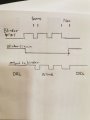
I would like to make a circuit that turns on my two front blinkers on my car permanently, and when the blinker is activated, the lamp should blink as normally.
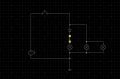
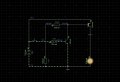
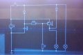
I have no experience in circuit designing, but i was thinking that maybe it's possible to use a transistor, mosfet or maybe a 555 timer somehow? and make 2 circuits to insert into each bulb wiring. My first design was to use a mosfet and a cap for delay, but the timing is too short (and i don't know what i am doing). Any suggestions? My poor attempt is included. The momentary switch is representing the blink relay. There are 2 bulbs on the circuit, one in the front of my cra that i want to controll, and one in my mirror that i want to behave as normal.
 

Attachments

geekoftheweek

Joined Oct 6, 2013
1,195
While many people on here have the knowledge to help you are stepping into legal issues that most will generally stay clear of. From what I could see the 10K and 1K (if I'm seeing it right) will drop the voltage probably far below what your gate voltage really needs to be. Other than that keep researching.
 

Thread Starter

Laban9393

Joined Dec 3, 2020
17
While many people on here have the knowledge to help you are stepping into legal issues that most will generally stay clear of. From what I could see the 10K and 1K (if I'm seeing it right) will drop the voltage probably far below what your gate voltage really needs to be. Other than that keep researching.
Thanks for the input! Regarding the legallity of it, it's legal in my country, and the modules that does this can be purchased. But where is the fun in that.
 

crutschow

Joined Mar 14, 2008
34,201
Does this do what you want?
The lamp is on until the blinker turns it off.
The P-MOSFET can be just about any with a Vds rating of at least 30V and an on-resistance low enough to keeps its dissipation below 1W (so it doesn't need a heatsink) when carrying the total lamp current.

1607029563346.png
 

Thread Starter

Laban9393

Joined Dec 3, 2020
17
Does this do what you want?
The lamp is on until the blinker turns it off.
The P-MOSFET can be just about any with a Vds rating of at least 30V and an on-resistance low enough to keeps its dissipation below 1W (so it doesn't need a heatsink) when carrying the total lamp current.

View attachment 224068
This would kinda work, but not really. Hooking this up would mean that the forward lamp (that is controlled with the circuit) would turn on and off opposite of the side and rear blinker. What i would like is to keep the lamp on as long as the blinker is not energised. Then when the blinker start pulsing, the circuit should turn off and thus the blinker is controlling the lamp. If the circuit has a on delay of example 1 second, the circuit should not turn the lamp back on for a steady light untill the blinker is turned off, as the blinker keeps pulling it high. Sorry if i made it sound too complicated, but hopefully you get the gist of it! Great attempt anyways
 

crutschow

Joined Mar 14, 2008
34,201
would turn on and off opposite of the side and rear blinker.
And why is that a problem?

The observers in the back can't see the front and vice-versa.
And even if they see the front and side at the same time, they won't be confused.
Might even better get their attention, which is what you want.
 
Last edited:

Thread Starter

Laban9393

Joined Dec 3, 2020
17
And why is that a problem?

The observers in the back can't see the front and vice-versa.
And even if they see the front and side at the same time, they won't be confused.
Might even better get their attention, which is what you want.
This is because all lights must blink together for it to be legal. Also both the front blinker and the side blinker on the outer rear wiew mirror can be observed from the front. So basically all i need is a circuit with an output that turns low by the high signal from the blinker, and stays off for 1 second before going high. Then the 500ms blink interval would keep this low.
 

Thread Starter

Laban9393

Joined Dec 3, 2020
17
I think i get the functionallity of the circuit. How i read it, it still would blink the front turn signal out of sync with the remaining blinkers. That is not what i want the circuit to do. But it's a nice effort guys. This is what i wanted to make, only it is missing the time delayed gate. If the gate could be delayed from turning on for 1 sec after the blinker goes low, the blinker relay would control the lamp while blinking, and the mosfet would only activate the daytime running light function i am after.
 

Attachments

eetech00

Joined Jun 8, 2013
3,847
I think i get the functionallity of the circuit. How i read it, it still would blink the front turn signal out of sync with the remaining blinkers. That is not what i want the circuit to do. But it's a nice effort guys. This is what i wanted to make, only it is missing the time delayed gate. If the gate could be delayed from turning on for 1 sec after the blinker goes low, the blinker relay would control the lamp while blinking, and the mosfet would only activate the daytime running light function i am after.
What is confusing (to me anyway) is you say it wouldn't be in sync with the remaining blinkers. but I haven't shown any other lights and blinkers except the existing blinker, switch and the DRLs, so how can that be? You'll have to figure out how to wire it to the new circuit.

So the way I understand it, you want to add "daytime running lights", but you want them to blink is sync with the corresponding turn signal light. I don't understand why the delay is needed.
 

Thread Starter

Laban9393

Joined Dec 3, 2020
17
What is confusing (to me anyway) is you say it wouldn't be in sync with the remaining blinkers. but I haven't shown any other lights and blinkers except the existing blinker, switch and the DRLs, so how can that be? You'll have to figure out how to wire it to the new circuit.

So the way I understand it, you want to add "daytime running lights", but you want them to blink is sync with the corresponding turn signal light. I don't understand why the delay is needed.
Let me explain. The car have 3 lamps on each side, connected in paralell on the output of the blink relay. The DRL function is only wanted on the front lamp, so in order to achieve this i need to add the circuit inline with that bulb, and add a diode to not keep the two other lamps from staying on. Hence if the circuit suggested above was installed, using the mosfet to blink the lamp then the two other bulbs would turn on, and the front bulb off. So if the mosfet would stay off for the duration that the blinker is blinking, this would work perfectly At least in my mindo_O
 

crutschow

Joined Mar 14, 2008
34,201
Here's the simulation of a circuit that (per post #1) does what you want. (But you seemed to have changed the requirements from post #1 to post #13).

It adds a transistor to generate the desired function of having the running lights while blinking then in sequence with the turn signal.

Note that the switch from the 12V that turns on the running lights (for top wire) is not shown.

1607104264949.png
 
Last edited:

Thread Starter

Laban9393

Joined Dec 3, 2020
17
Not quite sure i inderstand what you mean with having the running lights while blinking? Did not get your design to work in my simulation, it just stays on all the time. I added the screenshot. The premises are the same as the first post? Maybe im just terrible at explaining:rolleyes:
I have attached the wiring here, and the switch represents the blinking signal from the relay to the bulbs. Only bulb 1 should have the desired DRL function of staying on solid while nothing happens, and when the blinking signal starts pulsing, lamp number 1 should start blinking just like the others. The yellow line is where i want to connect the output of the circuit to drive the lamp, and the diode would stop lamp 2 and 3 from lighting up while using the drl circuit. Maybe a 555 timer could be used to delay a n channel mosfet inline with bulb 1 and in paralell with the blinking signal to start conducting?
And thank you for the suggestions, very informative and interesting trying them out and seeing the different solutions.
 

Attachments

eetech00

Joined Jun 8, 2013
3,847
Not quite sure i inderstand what you mean with having the running lights while blinking? Did not get your design to work in my simulation, it just stays on all the time. I added the screenshot. The premises are the same as the first post? Maybe im just terrible at explaining:rolleyes:
I have attached the wiring here, and the switch represents the blinking signal from the relay to the bulbs. Only bulb 1 should have the desired DRL function of staying on solid while nothing happens, and when the blinking signal starts pulsing, lamp number 1 should start blinking just like the others. The yellow line is where i want to connect the output of the circuit to drive the lamp, and the diode would stop lamp 2 and 3 from lighting up while using the drl circuit. Maybe a 555 timer could be used to delay a n channel mosfet inline with bulb 1 and in paralell with the blinking signal to start conducting?
And thank you for the suggestions, very informative and interesting trying them out and seeing the different solutions.
I now understand what your after. In the previous circuits, the DRL is held on but is in opposite state when "blinking" is initiated.
The circuit becomes more complex if we need to detect when the blink signal is "blinking" as opposed to knowing the position of the turn signal switch. Is it possible to get the position of the turn switch as a non-blinking signal? In other words, Left=12v(steady), Rht=12v(steady), Off=0v(steady)? The Left and Right signals will need to reflect the turn signal position.
 

crutschow

Joined Mar 14, 2008
34,201
Not quite sure i inderstand what you mean with having the running lights while blinking?
I mean it's steady on as a running light with no turn signal, and blinks when the turn signal is on.
Did not get your design to work in my simulation,
No.
I got it to work in my simulation, and don't quite understand yours.
Your complete requirements are still confusing to me.
Do you want some running lights to blink with the turn signal, and some to turn off with the turn signal?

Is there something wrong with my circuit?
 

Thread Starter

Laban9393

Joined Dec 3, 2020
17
I now understand what your after. In the previous circuits, the DRL is held on but is in opposite state when "blinking" is initiated.
The circuit becomes more complex if we need to detect when the blink signal is "blinking" as opposed to knowing the position of the turn signal switch. Is it possible to get the position of the turn switch as a non-blinking signal? In other words, Left=12v(steady), Rht=12v(steady), Off=0v(steady)? The Left and Right signals will need to reflect the turn signal position.
Yes exactly! That was why i tried to use a P channel mosfet to drive the drl function, and when the blinker starts it pulls the gate high, turing off the mosfet and directly blinking the bulb from the signal. I then need it to stay off for 1 or 2 second so the drl is not activated while blinkinn occurs, thus overriding the blinking. If that is correct and makes any sense heh.. I was not planning to know the position of the turn signal switch, and to just install the circuit in each of the front lamps wiring loom. The right and left side blinking signal comes from a control unit wich one wire goes to the left side 3 bulbs, and the other signal wire goes to the right side 3 bulbs. It is the only signal i have to work with
 

Thread Starter

Laban9393

Joined Dec 3, 2020
17
I mean it's steady on as a running light with no turn signal, and blinks when the turn signal is on.
No.
I got it to work in my simulation, and don't quite understand yours.
Your complete requirements are still confusing to me.
Do you want some running lights to blink with the turn signal, and some to turn off with the turn signal?

Is there something wrong with my circuit?
Requirements: Bulb right side forward and left side forward is normally on, while the two wing mirror bulbs and the two taillight bulbs is off. When blinking to the left, the drl function on the left side must stop, and the bulbs on the left side all blink in harmony with each other. The same on the other side when blinking the other way. When blinking stops, the drl function must resume. Each side is connected as 3 bulbs in paralell on the respective blinker output. Hopefully this was a better explanation:)
 

eetech00

Joined Jun 8, 2013
3,847
Yes exactly! That was why i tried to use a P channel mosfet to drive the drl function, and when the blinker starts it pulls the gate high, turing off the mosfet and directly blinking the bulb from the signal. I then need it to stay off for 1 or 2 second so the drl is not activated while blinkinn occurs, thus overriding the blinking. If that is correct and makes any sense heh.. I was not planning to know the position of the turn signal switch, and to just install the circuit in each of the front lamps wiring loom. The right and left side blinking signal comes from a control unit wich one wire goes to the left side 3 bulbs, and the other signal wire goes to the right side 3 bulbs. It is the only signal i have to work with
The picture in post #11, what is the "blinker circuit"? Is that a signal that stays low while the bulbs are blinking, then goes normally high? Is it available as an input?

What signals are available as inputs to the new circuit?
 
Top