 Facebook
 Google
 GitHub
 Linkedin
/* UPDATED */
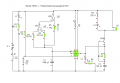
The circuit should work like this, upon turning on S1, L1 will be on and the circuit will be on standby. Once I press S2, the timing will be initiated and timing will begin (time is chosen by RS1 rotary switch). This will cause L2 to turn on. After the timing has been complete, L3 and B1 will be on for approx. 0.5 seconds.
This has worked in the Crocodile Clips simulation software.
However, when I tried it in real-life it did not work, the B1 and L3 were on right after I completed S1, and after I pressed S2, L3 turned off, L2 turned on, but B1 was still on. I tried S3 (Push to break) to no avail.
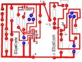
I have also attached the PCB diagram, could there be a problem there?
Moreover, my friend has the same transistor section in his circuit but it works fine for him.....
P.S I am using two circuit boards so the +a and +b seen in the PCB screenshot are merely wires linking them together.
The circuit should work like this, upon turning on S1, L1 will be on and the circuit will be on standby. Once I press S2, the timing will be initiated and timing will begin (time is chosen by RS1 rotary switch). This will cause L2 to turn on. After the timing has been complete, L3 and B1 will be on for approx. 0.5 seconds.
This has worked in the Crocodile Clips simulation software.
However, when I tried it in real-life it did not work, the B1 and L3 were on right after I completed S1, and after I pressed S2, L3 turned off, L2 turned on, but B1 was still on. I tried S3 (Push to break) to no avail.
I have also attached the PCB diagram, could there be a problem there?
Moreover, my friend has the same transistor section in his circuit but it works fine for him.....
P.S I am using two circuit boards so the +a and +b seen in the PCB screenshot are merely wires linking them together.
Attachments
-
 12.6 KB Views: 32
 -
 70 KB Views: 24
Last edited:


") , I'm not really familiar with the 555-IC. I did take a look at the article but I didn't understand it fully. I'll take a look at it again.
, I'm not really familiar with the 555-IC. I did take a look at the article but I didn't understand it fully. I'll take a look at it again.


