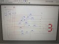
That's bad since you have the switches set to 6. You had better replace those inverters or you're going to be marked down.
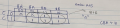
Show your kmaps and equations so we don't have to trace your circuit. It's not as bad as some student work I've seen, but it's definitely not what I'd consider easy to read.
You can print to B&W PDF from Multisim. We won't have to deal with Moire patterns if you did that.
Where in the instructions did it say you couldn't use a 3 input NAND gate?
EDIT: I checked the logic for segments 'a' and 'c'. You made the same mistake on both.
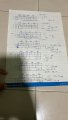
The truth table you posted did not show the don't care counts. Neither did your Kmaps. And I don't see where you attempted to post your equations.
You posted incomplete maps and equations that weren't simplified as much as they could be because you weren't using don't cares properly (post #33). I told you as much in post #34.
Did you finish the problem? By my count, you made a dozen mistakes and could have corrected them in 10-15 minutes after you showed me enough work and I showed you the mistakes you were making.
I could have also shown you how to draw more readable schematics. There's more art to that than science. Some people never learn it.
I see that you checked the thread, but didn't have anything to say. I'll try to help you anyway.
Your work is sloppy:
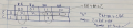
For "b", you have 3 equations. Two are the same and one is wrong. You don't show the groupings in the kmap that would yield the correct equation. You should cross out the incorrect equations.
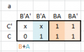
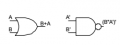
Your equation for "a" is correct. B+A is not equivalent to (BA)'.
De Morgan's theorem says to negate the inputs and output and change the connector, so that would be (B'A')'.
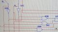
Your schematic has unnecessary wire crossings, jogs, unnecessary space, and scenic routes. I dislike very much the "smart" routing Multisim suggests. You can encourage cleaner routes by holding the shift key. You can also move connection dots and wires around after Multisim has done something stupid.
We don't overlap component designators with symbols. We don't route wires over text or symbols.
One thing I learned from using the free version of Multisim (MultisimBlue or something like that) is that it sometimes forgets about connections. I got into the habit of grabbing components and moving them around whenever something wasn't working correctly to make sure no connections were forgotten.
In your first post you said (or it seems you meant to say) that you were told that 0 and 1 can never happen, the inputs can't happen - that's not quite the same as "ignoring" them, assuming those two values can never happen might be relevant, I don't know, it might have some bearing on the minimum number of gates - not saying it does, just saying that ignoring something isn't always the same as that something never being possible.

 Facebook
 Google
 GitHub
 Linkedin