Up/down sequence counter using 74191

Thread Starter

Eman_Ali

Joined Nov 28, 2014
5
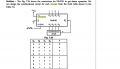
Hi all, I need to make up/down counter using 74191 that generates the following sequences
9, 8, 7, 6,5,4,9,...
1,2,3,4,5,6,....
The Ic has 4 inputs A,B,C,D. How will I connect my 6-inputs (each of 4-bits ) to the Ic.
Thanks.
 

Attachments

WBahn

Joined Mar 31, 2012
29,979
First, you need to show YOUR attempt to solve YOUR homework problem.

You also need to express your problem more clearly. You are saying that you have to make a single counter that generates two different sequences. What determines which sequence is produced? Are you supposed to be able to switch between the two sequences at any time by flipping a switch? What?

What are these six four-bit inputs you are talking about. That's 24 bits of input. The IC only has a total of eight input pins, and that's counting the clock.
 

shteii01

Joined Feb 19, 2010
4,644
Each of your numbers is represented by 4 bits (A, B, C, D).
Now it is time to write a truth table. Go ahead and write it out.
 

Thread Starter

Eman_Ali

Joined Nov 28, 2014
5
Ok,I have worked on displaying only the first sequence (9,8,7,6,5,4,9..) for now, if the counter output is other than (9 to 4) the digit 9 is loaded. The pin (up/down) is connected high. I used a k-map to simplify the out put Y. Attatched is my attempt. Ive done it on bread board but it only displays (3 then 2). Do you have any suggestions ? Thanks
 

Attachments

WBahn

Joined Mar 31, 2012
29,979
Things look okay at first glance. Your direction pin isn't "up/down" it is "down/up". It makes a difference. Think of the name as being two different but equivalent names, "down" and "/up". A HI input means that "down" is TRUE and, equivalently, that "NOT up" is TRUE. Avoids a lot of confusion. Also, on your diagrams, be sure that you indicate that the Load signal is active-LO. You can do that with a bubble at the pin or by calling the signal "/load".

Do you have access to an oscilloscope or logic analyzer so that you can look at the signals on the various pins? It may be nothing more than a simple breadboarding error.
 

shteii01

Joined Feb 19, 2010
4,644
Ok,I have worked on displaying only the first sequence (9,8,7,6,5,4,9..) for now, if the counter output is other than (9 to 4) the digit 9 is loaded. The pin (up/down) is connected high. I used a k-map to simplify the out put Y. Attatched is my attempt. Ive done it on bread board but it only displays (3 then 2). Do you have any suggestions ? Thanks
That truth table looks too simple.
Your truth table should have Present State, Next State.
 

shteii01

Joined Feb 19, 2010
4,644
Ok, I see your point. I might have been thinking of designing from ground up, but you don't need that, you already have 74191 that does the counting.
So.
1) Select down count.
2) Load 9.
3) Enable count.
4) You counted down to 4. The next transition from 4 to 3, what happens here? Stop?
 

WBahn

Joined Mar 31, 2012
29,979
That truth table looks too simple.
Your truth table should have Present State, Next State.
Since he is using a counter, his diagram becomes more generalized in which he has one "state" which includes all counter values for which the counter decrements and another "state" which includes all counter values for which the counter resets.
 

WBahn

Joined Mar 31, 2012
29,979
Ok, I see your point. I might have been thinking of designing from ground up, but you don't need that, you already have 74191 that does the counting.
So.
1) Select down count.
2) Load 9.
3) Enable count.
4) You counted down to 4. The next transition from 4 to 3, what happens here? Stop?
No, he goes back to 9. This is implied by his first post where he has "9,8,7,6,5,4,9,...". Since the counter has an asynchronous reset, he needs to trap a count value of 3 (which should last for such a short time that it can't be seen on the display, although any circuit looking at the output might well respond to it -- a point that is often overlooked in digital design classes).
 

shteii01

Joined Feb 19, 2010
4,644
Yes, Do you think its a bread board problem or a problem with the steps of design its self ?
How do you generate clock signal?
If you run it slow, you could just hook up led to Q0-Q3 and see your 74191 outputs. Like the first value should be 9. You said that you saw 3, I assume on 7 segment. So you are not really seeing output of 74191. It may or may not matter, I admit. But since you are not getting right result you have to troubleshoot the circuit and it makes sense to start with the first block of the circuit.
 

WBahn

Joined Mar 31, 2012
29,979
Yes, Do you think its a bread board problem or a problem with the steps of design its self ?
Given the quick look I gave it, I think your design is okay. I would look at the implementation. One way to do this, if you can't spot something wrong fairly quickly, is to simplify the design and just feed back, say, Q2 to the /load input and reset the counter to something that has Q2 asserted, such as a value of 7. This should then count 7,6,5,4,(3)7,... where (3)7 means that it goes to state 3 momentarily before going to 7.
 

WBahn

Joined Mar 31, 2012
29,979
How do you generate clock signal?
If you run it slow, you could just hook up led to Q0-Q3 and see your 74191 outputs. Like the first value should be 9. You said that you saw 3, I assume on 7 segment. So you are not really seeing output of 74191. It may or may not matter, I admit. But since you are not getting right result you have to troubleshoot the circuit and it makes sense to start with the first block of the circuit.
Slowing your clock is a very good idea. If you know how, you could even make a single-step circuit so that you get one clock pulse each time you press a button. Something like this really should be one of the first circuits that digital courses have students implement as it is very useful.
 

shteii01

Joined Feb 19, 2010
4,644
Slowing your clock is a very good idea. If you know how, you could even make a single-step circuit so that you get one clock pulse each time you press a button. Something like this really should be one of the first circuits that digital courses have students implement as it is very useful.
We did these circuits in lab and we used frequency generator, so we could slow it down or speed it up pretty much as much as we liked. Made for pretty light show, at times.
 

KJ6EAD

Joined Apr 30, 2011
1,581
One way to implement what WBahn and shteii01 have suggested is to set up a 556 timer so one timer is a monostable to generate a single clock pulse from a button push and the other timer is a slow astable. This is a convenient tool for breadboarding digital circuits.
 
Top