Facebook
 Google
 GitHub
 Linkedin
Hello all,
I am in the process of hooking up a LiDAR to a GPS and have some concerns about my PPS signal. I am not very experienced in electronics and can use some help.
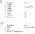
For the LiDAR to work, it requires an NMEA sentence as well as 1PPS with a pulse width of 100ms. Positive/Negative pulse polarity can be adjusted accordingly. These settings are configurable in the software that came with the GPS/LiDAR.
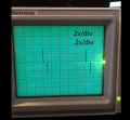
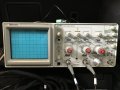
When reading the signal out of the GPS on the PPS output pin using a Tektronix 2235 Oscilliscope, I receive the signal in the attached image "TIMINGIO_PPS_Edit.png". It occurs once per second. I have added some annotations to the image to help describe what is happening as well as the settings that were used.
Does this PPS signal make sense to any of you? What could potentially be causing this shape?
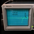
The attachment "ANTARIS_PPS_Edit.png" is a reading of the PPS signal coming from a test GPS, in the correct signal characteristics as needed by the LiDAR. Once again, I have added some annotations. I hope this helps confirm that my Oscope is not broken or otherwise.
We are in the process of obtaining a digital oscilloscope to confirm the signal but I'd still like to hear any suggestions you all may have in case a differenc oscope produces the same results.
Thanks in advance.
I am in the process of hooking up a LiDAR to a GPS and have some concerns about my PPS signal. I am not very experienced in electronics and can use some help.
For the LiDAR to work, it requires an NMEA sentence as well as 1PPS with a pulse width of 100ms. Positive/Negative pulse polarity can be adjusted accordingly. These settings are configurable in the software that came with the GPS/LiDAR.
When reading the signal out of the GPS on the PPS output pin using a Tektronix 2235 Oscilliscope, I receive the signal in the attached image "TIMINGIO_PPS_Edit.png". It occurs once per second. I have added some annotations to the image to help describe what is happening as well as the settings that were used.
Does this PPS signal make sense to any of you? What could potentially be causing this shape?
The attachment "ANTARIS_PPS_Edit.png" is a reading of the PPS signal coming from a test GPS, in the correct signal characteristics as needed by the LiDAR. Once again, I have added some annotations. I hope this helps confirm that my Oscope is not broken or otherwise.
We are in the process of obtaining a digital oscilloscope to confirm the signal but I'd still like to hear any suggestions you all may have in case a differenc oscope produces the same results.
Thanks in advance.
Attachments
-
 326.5 KB Views: 39
 -
 420.8 KB Views: 38