 Facebook
 Google
 GitHub
 Linkedin
Ahh i see. Reading here that "...one [conductor] carries the signal and the other carries the inverted signal" made me believe so. Specifically, PPS Return + ground produced what appeared to be the inverse wave of PPS Out + ground using the oscilloscope. I got my hands on a digital oscope from Amazon and was able to confirm the Tek 2235 readings I was getting before (using PPS out and Signal Ground).
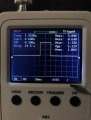
Anyways, I probed PPS Out and used the ground lead to PPS Return. I attached a screen shot of the PPS signal from this reading. Don't mind the top left signal characteristics, it just happened to change when I took the picture. They typically show 1hz,10% duty etc.
Oh, no. I might have led you to confusion here. The Antaris GPS was a test for us to see if we could get our LiDAR to "Lock" onto the PPS and NMEA sentences we sent it. From there we looked at the characteristics of the Antaris GPS to see what the NMEA and PPS signals should look like on our "actual" GPS. This actual GPS we are trying to use is in an enclosed box that opening it would most likely be a very last resort. The pinout of one of the previous replies and the left screenshot on the original post is from the actual GPS.
On the topic of the Antaris GPS, there is an adapter board that connects to the 8pin header of the GPS and turns it into RS232. There is an IC on the adapter which is likely what you're talking about. I'm not so much concerned about the Antaris GPS at this point, which now reading through the past replies, I can see the confusion. Sorry about that.
Thank you.
Attachments
-
 41.4 KB Views: 3


