OK, and now I am assuming that the op-amp supply is bi-polar, referenced to some "zero voltage" common. Which may, or not, be "ground".
The intention is to reduce the impedance of the supply circuit to common and each other at the higher frequencies, thus reducing unwanted signal paths that may be causing oscillations.
What is interesting is that I do not recall any serios discussion of supply bypassing in any of my college courses.
OK, I did not explain adequately, my fault. This is not a bipolar supply circuit, which is made very clear by the fact that the + inputs are biased to about half Vcc.: R9 &R10,, R3 & R4 are responsible for that.
bipolar power scheme will have a zero voltage common as well as both positive and negative supplies that have their other side connected to that "zero voltage line. The bipolar scheme offers the benefit that the output voltage will usually be close to zero with no signal, which is often quite convenient. The single supply scheme usually has the zero signal output biased at about half of the supply voltage (Vcc). The primary advantage is only one power supply required.
Oh, ok. I think I understand the advantage. Unfortunately in the music world, single output supplies are the norm, 9v being the standard with 12, 15, 18v sometimes being options.
Oh, ok. I think I understand the advantage. Unfortunately in the music world, single output supplies are the norm, 9v being the standard with 12, 15, 18v sometimes being options.
Especially with battery powered "stomp boxes" and many others as well, that is the case. But on this very same forum is a situation with a Bheringer brand studio monitor running bipolar power in all sections. So now you have a small addition to your knowledge base, and I am reminded that not everybody has the same technical background. Thanks for that. I do own one of those single supply pedals, and original "CryBaby" pedal, which I believe is a variable band pass filter device. It comes from an era when ICs were neither common nor cheap.
I put a 0.1u across Vcc+ and GND, no effect. However, I noticed that when I touched the single pot for the gain stage, it acted like a LPF, definitely muffled the helicopter sound. Touching the dual pot for the HPF had no effect. And moving my hand around the circuit changed the sound too, probably shielding it.
Tomorrow I should have time to drill some holes in a metal 1590A, I'm hopeful that will help.
It's interesting though, because the simple circuit I've been playing through is in a 3D printed box and it doesn't pick any noise up... but it doesn't have an op amp or any amplification, simply electret mic power and 3 power supply caps. But once you add the op amp, it gets more complicated.
Especially with battery powered "stomp boxes" and many others as well, that is the case. But on this very same forum is a situation with a Bheringer brand studio monitor running bipolar power in all sections. So now you have a small addition to your knowledge base, and I am reminded that not everybody has the same technical background. Thanks for that. I do own one of those single supply pedals, and original "CryBaby" pedal, which I believe is a variable band pass filter device. It comes from an era when ICs were neither common nor cheap.
Huh. Behringer is a mixed bag. Historically they were cheap, cheap, cheap. But in recent years they have began to impressed me. Their X32 mixing board is a fantastic value, and they have a few other musical items that are pretty darn good for the money. It's interesting they use a bipolar supply. I suspect larger items like amps and speakers, etc. could afford more complicated power supplies both cost and space wise. But in the pedal arena it hasn't taken off yet.
I dislike center negative connections rather strongly. Because I had a lot of smoke excape from a fully remote controlled color camera that used center negative on the power connector. three axis panning plus zoom, focus and iris control All smoked because of center negative.
I dislike center negative connections rather strongly. Because I had a lot of smoke excape from a fully remote controlled color camera that used center negative on the power connector. three axis panning plus zoom, focus and iris control All smoked because of center negative.
Blame Boss. When they came out with pedals back in the 70s/80's they were center negative and to this day 90% of all musical stuff I've ever seen are center negative. Although there are many companies who are trying to change the tide with center positive, it's hard (requires adapters) because most musicians just want it to be all the same standard Boss 5.5/2.1mm center negative.
So it has something to do with the opamp, it's not RF noise. When I breadboard just the first part (left half) of the circuit without the opamp, there are no helicopter sounds. Taking the output at the voltage divider between R2 and R3.
But when I add in the opamp, using a gain of 1 (no pot, shorting pin2 to pin6), the helicopter sounds are there... around 6-8 Hz. It doesn't matter whether the mic is hooked up or not.
OK, here is a possibility, or maybe not. The only other thing connected to the input is that voltage divider. Noise on the V+ line would be amplified. So try a temporary capacitor across R3. or directly from pin 3 to pin 4, and see if the noise changes. It seems that if the noise is not generated inside the IC, or coming in the power pins, it has to be coming in via an input. No other connections.
Are the brown capacitors ceramic type? Ceramic capacitors are '"microphonic" and produce noises if vibrated or moved.
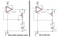
The- input of the opamp is very sensitive then the slider of the gain pot should be connected to the opamp output, not the - input.
The metal housing of the gain pot should be bolted to 0V as a shield.
The small yellow caps (0.1u) are monolithic multilayered ceramic caps. If not ceramic, then what type are better?
But I think I figured it out. I was looking at the datasheet of the TL071/72 and noticed a couple of their examples had a 100pF across the output. I added this and while it didn't eliminate the helicopter noise completely, it definitely reduced it significantly. @Audioguru again I'm interested in your thoughts on this. This 100 pF is parallel with RL (R5 below). The only difference is your circuit has a 22u.
I did this to the preamp/HPF circuit as well (below), and also reversed the 9v jack polarity so the jack housing is grounded (and not Vcc!). The very tiny helicopter sounds left I can cut using an input gate on the Helix. Played it for a while, nice being able to adjust the level of the mic in relation to the other pickup. I'm not sure exactly where the HPF is set, but it's probably 500-600 Hz.
An opamp is not supposed to have a capacitor to ground at its output. If there is enough capacitance then the capacitor will cause enough phase shift to cause oscillation. That is why R6 is in series with the opamp output to isolate the capacitance of a shielded output cable. The datasheet has 100pF to show that the opamp can drive it not too badly.
The helicopter sounds are from RF interference, I found 2 solutions:
1) a grounded enclosure. Previously I put the circuit in a metal enclosure... but because the dc jack was negative center, I didn't mount it to the enclosure (because it shorted out), so it was floating. Well that didn't do any good. Once I switched the jack polarity and made it positive center and mounted it to the enclosure, it did it's job.
2) the 100 pF across the output of the op amp also works withOUT an enclosure... but this is not how op amps are suppose to work.
@Audioguru again and others have mentioned before how important a grounded enclosure is, but I didn't fully understand the ramifications. So I learned some stuff this weekend, thanks for all the input.
OK, and itis interesting that the interference was from an external source. Now I am wondering what sort of external source, for my own education. I have been fortunate to have only encountered outside interference with a correctly wired sound system once, which was a case of the power wires for the sound system ran in a long conduit next to wires feeding a bank of 1200watt triac dimmers. The fix for that interference noise problem was to open the green-wire ground connection of the sound system. The ultimate solution will be to install a separate power feed from the breaker panel to the sound system. Not simple in a cement block construction building.
 Facebook
 Google
 GitHub
 Linkedin