Because R4 and C3 form a low pass filter for the power supply, that gets rid of any ripple on the battery supply caused by the op-amp having to drive an external load.
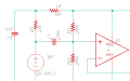
Connect it like this is what I'm wondering, with R4 between R1 and R2 so that R2 and R3 form a proper 1/2 supply. C3 and R1 are still connected the same way.
Connect it like this is what I'm wondering, with R4 between R1 and R2 so that R2 and R3 form a proper 1/2 supply. C3 and R1 are still connected the same way.
If you do that, you inject all the noise from the supply back into the signal.
Remember that there is a difference between the perfect voltage source in SPICE and a real battery, or the output of a switched-mode supply and all its high-frequency ripple.
Imagine your supply is not simply 9V DC, but 9VDC plus 100mV AC at 50kHz. You can simulate that in SPICE.
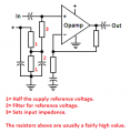
The signal at the amplifier input is then 4.5V+50mV AC + the signal from the microphone. That gets amplified by the op-amp and the signal at the output is the microphone signal plus 50mV multiplied by the amplifier gain of high frequency noise. You won’t hear it at 50kHz, but it could make quite a mess of the signal from following stages.
Oh, great explanation. So the LPF is not only filtering the mic power, but ALSO the input to the opamp. But if R4 is after R2 (before R1), then that AC noise gets applied directly to the input of the opamp. I get it. Thanks.
Because R4 and C3 form a low pass filter for the power supply, that gets rid of any ripple on the battery supply caused by the op-amp having to drive an external load.
OK, so if R4 and C3 form a power supply low pass filter for the mic and opamp signal input, then what is C1 for? It doesn't have a resistor to pair with for a filter.
Yet more filtering power supply filtering (you can never have too much*). It forms another RC filter where R is the output impedance of the battery or the power supply.
[Edit] *or perhaps you can, after three stages, and with and amplifier in it, you have all the parts to make a phase shift oscillator.
RC filters require R and C. There is always R (and C) inherent in every circuit, i.e. resistance in every connection, even in the capacitor itself.
You can alter the effect of the RC filter by adding more resistance in the circuit.
One of the reasons you need several filters at different frequencies is the parasitic components.
Every capacitor has series inductance (think how they are made as a spiral). In the datasheet you will find the self-resonant frequency. Above that frequency inductance dominates and your low-pass RC filter turns into a high-pass LR filter, and it is no longer blocking high-frequency interference, even though it will be doing a sterling service at lower frequencies. You then need another filter with high-frequency components to block the high-frequency interference.
So I built this circuit on a PCB from Osh Park. But it was noisy. On the advice of @Audioguru again and @sghioto I got a better power supply and changed the input wiring to a shielded cable. Muuuch better. But there is still a put-put helicopter type sound. This made me think of a post from a while back:
If you delete the very low cost of R10 and connect R11 to the R3 and R4 divider then you will still have some positive feedback (through R2POT) even with C5 and C9 connected. The result might be motor boat (put, put, put) sounds.
That sound might be some portion going into s high frequency oscillation, building until it saturates and blocks itself. How about bypass capacitors right at the amplifier terminals. Those little 0.1 or 0.47 Mfd small ones? Cheap and easy to add under the PCB and known to solve strange problems. If you have an oscilloscope that could make the diagnostics much simpler.
That sound might be some portion going into s high frequency oscillation, building until it saturates and blocks itself. How about bypass capacitors right at the amplifier terminals. Those little 0.1 or 0.47 Mfd small ones? Cheap and easy to add under the PCB and known to solve strange problems. If you have an oscilloscope that could make the diagnostics much simpler.
No I don't have an O-scope, but I'd like one. I have an assortment of caps you suggest. What terminals would I jumper with them? View attachment 286691
 Facebook
 Google
 GitHub
 Linkedin