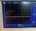
The PWM signal is the input, the other is the output. I checked Pad connections and everything is well connected as well as the 12V power supply. I understand that the op-amp is probably not fast enough, but signal distortion shouldn't be as much as this.
I tried it, but no significant difference. I tried to send a 3.3V DC signal with no AC attributes. But somehow the output was exactly the same as the output when connected to the PWM signal.
By the way: In post #1 the signal is described as "a PWM signal with a 50% duty cycle. IF that is really a CONSTANT AMPLITUDE signal then a logic gate will be a better choice. OR, is it a PAM (pulse AMPLITUDE Modulated) signal, which will benefit from an actual amplifier.
The PWM signal is the input, the other is the output. I checked Pad connections and everything is well connected as well as the 12V power supply. I understand that the op-amp is probably not fast enough, but signal distortion shouldn't be as much as this.
You have ringing on the output which is more likely a layout or output load problem, not an op amp problem per se.
What is the output load resistance and capacitance?
A small resistor (e.g. 100Ω) directly in series with the output may help.
The shown vertical sensitivity is 1V/div.
Are you sure the probe is 10:1?
The situation has changed, I'll explain it now. Firstly I was using the op-amp to isolate the output terminal of a logic level shifter from the input of the clock input of a CCD. I have decided this is not of use anymore and I will not be using an Op-Amp for that(I found out when testing the board that it was not necessary). For this purpose i was driving the Op-Amp with a true constant PWM signal. But that idea is scrapped, I will however need an Op-Amp another purpose. For isolation of the terminal from the CCD output to the ADC input. The CCD output will be an AC signal with varying amplitude.
To adress your response, I tried adding a resistor in series but that didn't help. The probe is also standard 10:1 probe and I can't change that, so I'm sure of it.
OK, first for the scope probe. Many of them have a compensation adjustment that is used along with the probe calibration terminal on the scope to allow the probe to accurately a good square wave.
The signal from the CCD will need an amplifier that has excellent frequency response and very low noise. Often called a video amplifier.
Did you say MHz you are definatly going to loose some voltage at that speed. I also see the same thing in the sim. Using microcap you can, just add a slider on our sig generator on Probe Transient, and you will see that boy drop as you increase the frequency. Also, I would wager that you likely have a clone, that will not match exactly to specs of the real deal. Fun thing to do is see if it matches the spec sheets with a function gen. Forget Microcap simulation does it match datasheet?
BTW Microcap is by far the best simulator out there. Folks don't like it because of learning curve but there is a reason it was a giant in the production world, and cost an arm and leg when it was a license product. It does it all. Its he linux of simulators.
BTW at that speeds I am sure you are never suppose to use an opamp. You need a comparator my friend, and a CMOS one at that. They are designed to do the fast stuff.
BTW at that speeds I am sure you are never suppose to use an opamp. You need a comparator my friend, and a CMOS one at that. They are designed to do the fast stuff.
So yeah from what I see in the microcap, it is showing exactly what you are seeing on your scope when I sim LM358
 Facebook
 Google
 GitHub
 Linkedin