Unity Gain Op-Amp

Thread Starter

Luckyguide

Joined Feb 28, 2025
35
Hi all,

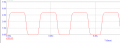
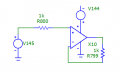
I'm using an op-amp and have set it to be unity gain in order to act as a buffer for a signal. However when i observe the output in the real world, it doesn't work as expected. The output is damped very much and doesn't work the same with my microcap12 simulation software. I have attached a simulation of the op-amp, the circuit was replicated in hardware exactly the same. The input is a 0-5V PWM signal with a duty cycle of 50% and frequency of 7.14MHz.

The used op amp is the ADA4851-1.
 

Attachments

dl324

Joined Mar 30, 2015
18,216
I'm using an op-amp and have set it to be unity gain in order to act as a buffer for a signal.
Meet the real world. There aren't any opamps that will operate the way you want.
The output is damped very much
I assume you're referring to the slope of the rising and falling edges.
doesn't work the same with my microcap12 simulation software
Bad simulator and a user too inexperienced to know it.
 

sghioto

Joined Dec 31, 2017
8,633
The input is a 0-5V PWM signal with a duty cycle of 50% and frequency of 7.14MHz.
Did not mention what the supply voltage is but for a 5 volt supply the input signal should be limited to 2.8 volts with that opamp
according to the spec sheet.
If the supply is 5 volts the input signal could be cut in half to 2.5 volts and set the amp gain to 2.
Something like this for simulation.

1746029951632.png
 

Thread Starter

Luckyguide

Joined Feb 28, 2025
35
The Voltage supply is 12V and can deliver as much current as is needed. I ran the simulation you suggested and it seems to give the same results. The result I get when observing with the oscilloscope is a dampened signal with slow rise and fall times, it swings between 2 and 3 volts.

I have knowledge of Op-Amps and am aware that they definitely do not operate as per the simulation. I did find an Op-Amp that is well within the limits of my requirements. But the output is considerably worse compared to what it should be in practice.
 

Attachments

Papabravo

Joined Feb 24, 2006
22,058
Opamps do not normally work in the RF ranges. What you're looking for may require a device with a HIGH gain bandwidth product and a VERY fast slew rate. Something like an OPA847. Like everything RF, layout is critical. I don't recommend a traditional breadboard, but rather Manhattan style dead-bug construction.
 

Thread Starter

Luckyguide

Joined Feb 28, 2025
35
I have a printed circuit board designed where the op-amp is used. I’ll give the OPA847 a shot as I can just switch them. Probably need an op-amp that is a lot more qualified for my application.
 

crutschow

Joined Mar 14, 2008
38,314
I have a printed circuit board designed where the op-amp is used
That ADA4851 op amp is a RR device which should have sufficient bandwidth and output slew-rate to operate properly as your sim shows, so your board configuration may be the problem.
Do you have a 10nF to 100nF decoupling capacitor directly from the op amps plus supply pin to a ground plane (you need a ground plane if you don't have one)?
 

crutschow

Joined Mar 14, 2008
38,314
Can you show a screen shot of the actual circuit response on the oscilloscope?

Are you using a 10:1 probe on the oscilloscope?
 
Top