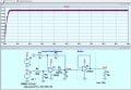
Unexpected result with peak detector circuit. Design help needed

ericgibbs

Joined Jan 29, 2010
21,621
Hi Sean,
With resistors R3 & R2 of both 1k, the gain is One for the Inverting Input, BUT Two for the Non Inverting Input.
So the R4 and R5 resistors 100k/96k form a voltage divider for the Input voltage Approx 0.49 attenuation, this also corrects for the forward voltage drop of the Bat54 diode.
E

Note: Assume a 5Vin signal so: 5Vin (1-0.49) = 2.550v *2gain
 
Last edited:

Thread Starter

SeanV123

Joined Nov 12, 2020
139
Hi Seanm
With resistors R3 & R2 of both 1k, the gain is One for the Inverting Input, BUT Two for the Non Inverting Input.
So the R4 and R5 resistors 100k/96k form a voltage divider for the Input voltage Approx 0.49 attenuation, this also corrects for the forward voltage drop of the Bat54 diode.
E
Thank you! But why do you need a 0.49 attentuation for vin?
 

Thread Starter

SeanV123

Joined Nov 12, 2020
139
Hi Sean,
With resistors R3 & R2 of both 1k, the gain is One for the Inverting Input, BUT Two for the Non Inverting Input.
So the R4 and R5 resistors 100k/96k form a voltage divider for the Input voltage Approx 0.49 attenuation, this also corrects for the forward voltage drop of the Bat54 diode.
E

Note: Assume a 5Vin signal so: 5Vin (1-0.49) = 2.550v *2gain
I have another question, how does this correct the forward voltage drop of the diode?
 
Hi Sean,
With resistors R3 & R2 of both 1k, the gain is One for the Inverting Input, BUT Two for the Non Inverting Input.
So the R4 and R5 resistors 100k/96k form a voltage divider for the Input voltage Approx 0.49 attenuation, this also corrects for the forward voltage drop of the Bat54 diode.
E

Note: Assume a 5Vin signal so: 5Vin (1-0.49) = 2.550v *2gain
I'm missing something: shouldn't it be 5Vin(0.49) instead of 5Vin(1-0.49)?

Thanks
 
Top