Understanding the most basic principles of current draw

Thread Starter

AlcoHelix

Joined May 15, 2017
20
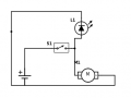
I'm missing some fundamental understanding of the current draw in the attached circuit. Power source is 2.8v (two AA batteries), LED is rated for 2.8v @ 20mA, and the load (I used a motor icon) is actually an electrical igniter that draws at least 1.3A. The issue is that the LED, connected in parallel, will not light when the switch is flipped. I assume it's because the igniter is sucking up all the current, nothing left for the LED? What phenomenon occurs that doesn't allow the paltry 20mA needed for the LED to flow to it?

And of course the final question: how do I change the circuit so that the LED does get enough current to light when the switch is thrown?

Thanks, as always.
 

Attachments

MrChips

Joined Oct 2, 2009
30,720
Batteries have internal resistances too. These are not indicated in a simple wiring or circuit diagram.
We don't know what is the value of this internal resistance.
Let us just assume, as an example that the internal resistance of each cell is 1Ω.
The total internal resistance of two cells is 2Ω.

The resistance of your igniter is 2.8V/1.3A which is about 2Ω also.
When you close the switch, the total circuit resistance is 4Ω. The igniter sees 1.4V. The LED sees 1.4V - not enough to turn on the LED.

LEDs should never be placed in parallel with a voltage source without some way of limiting the current.
Try putting a 10Ω or 22Ω resistor in series with the LED to protect the LED from burning out.
Now try it with bigger batteries, fresh D-size cells for example, which have lower internal resistance.
 

shteii01

Joined Feb 19, 2010
4,644
You have a current divider.
Since both devices are in parallel, they see the same 2.8 V. However, the current will leave the switch, enter the node and divide/split into two smaller currents, one will go to the igniter, other will go to led.

Since led brightness is controlled by the current, lack of led light tells us that it does not get enough current. It would be helpful if you could stick multimeter in series with led and measure the current going through led.
 

Thread Starter

AlcoHelix

Joined May 15, 2017
20
MrChips, I had a feeling that adding a resistor to the LED would somehow help the problem, but I don't understand it and I'm hoping you can school me on what the different resistances values in the circuit mean and how to compute them. I'm sure it's all Ohm's Law, but I don't quite understand how to apply it. My first instinct is that *adding* resistance to the LED would *reduce* the voltage or current going to the LED, but that's not the case, right? Or maybe it does reduce the current, but .... something else? I don't seem to have a solid grasp of: do resistors limit voltage or current or both or ::brain_melt::

shteii01, yes, that makes sense, the LED and the igniter are in parallel, so they should both see 2.8V. And I would think (and have always assumed?) that each load would "take" whatever current it required, assuming there was enough current to do what it needed. Are you saying that the LED is somehow getting *too much* current? It should only need a tiny 20mA to power to full brightness? This seems like such a childishly simple problem, but I don't get it.

blocco a spirale, I have confirmed that the LED still works. At first I thought I did blow it, that somehow it got smoked from some mistake on my end, but then I tried just connecting the 2.8V to the LED and voila, it still lights fine. The igniter, well, we'll just "let the mystery be"... =)
 

MrChips

Joined Oct 2, 2009
30,720
MrChips, I had a feeling that adding a resistor to the LED would somehow help the problem, but I don't understand it and I'm hoping you can school me on what the different resistances values in the circuit mean and how to compute them. I'm sure it's all Ohm's Law, but I don't quite understand how to apply it. My first instinct is that *adding* resistance to the LED would *reduce* the voltage or current going to the LED, but that's not the case, right? Or maybe it does reduce the current, but .... something else? I don't seem to have a solid grasp of: do resistors limit voltage or current or both or ::brain_melt::

shteii01, yes, that makes sense, the LED and the igniter are in parallel, so they should both see 2.8V. And I would think (and have always assumed?) that each load would "take" whatever current it required, assuming there was enough current to do what it needed. Are you saying that the LED is somehow getting *too much* current? It should only need a tiny 20mA to power to full brightness? This seems like such a childishly simple problem, but I don't get it.

blocco a spirale, I have confirmed that the LED still works. At first I thought I did blow it, that somehow it got smoked from some mistake on my end, but then I tried just connecting the 2.8V to the LED and voila, it still lights fine. The igniter, well, we'll just "let the mystery be"... =)
Basically everything you have said is correct.

Adding the resistor is not to help the problem you are having. The resistor is to save the LED from burning out. You want to avoid connecting an LED to a battery or any voltage source if you do not limit the current. You can do this with a resistor.

Let us assume that the max voltage of the LED is 2.2V (This is different for different colour LEDs). Let us assume that the recommended LED current is 20mA.
Let us say the battery voltage is Vs.
The resistor in series with the LED has to drop the excess voltage.
Thus, R = (Vs - 2.2V)/20mA

If Vs = 2.8V as example, R = (2.8 - 2.2)/0.020 = 0.6/0.020 = 30Ω

The problem is that the battery voltage is so close to the operating voltage of the LED that any small increase or decrease of the battery voltage would have a significant effect on the brightness of the LED.

Now, suppose Vs = 12V
R = (12 - 2.2)/0.020 = 490Ω

The higher series resistance means that the current is not going to be different by much if Vs is different from 12V.

Your problem: as already stated, your battery voltage drops below the operating voltage of the LED and hence does not light. You need a higher capacity battery such as D-cells.

If you increase the battery voltage, three cells in series for example, you must recalculate the required series resistance otherwise you will blow the LED.
 

Thread Starter

AlcoHelix

Joined May 15, 2017
20
So the LED I am using is rated for 2.8V, so it's exactly matched to the power source, but it sounds like maybe the igniter is causing too much of a draw and either sucking up all the current or dropping the voltage too low to properly light the LED? Is there a way to simply know which it is, or do I need to meter it and check? If I had larger batteries, like D cells (2 AAs just fit so well in the enclosure I have, so I really hope I can keep it 2 AAs), then I'd perhaps lower internal resistance and maybe more current to deal with? I know I'd have more mAh, longer battery life, but again, I'm hoping to stick with the 2 AAs for the enclosure.

Understanding all of this will help me a lot. And then the next question will be: How do I modify my circuit to somehow ensure that 2.8V @ 20mA is always available to light the LED, no matter what the igniter pulls? I now know for sure that running the two in parallel circuits is not the correct answer!
 

#12

Joined Nov 30, 2010
18,224
I really hope I can keep it 2 AAs
Not a chance!

MrChips used 2.2 volts, probably because that's about right for a red LED. LEDs need higher voltage as they go to smaller wavelengths of light. Red>green>blue>white
What you don't seem to be getting is that a AA battery has no chance of delivering an amp without serious loss of voltage, and a Light Emitting Diode is not a light bulb, it's a diode.
The 2.8 volt rating means that's the break-over voltage at 20 ma. Try giving it 2.6 volts and nothing will happen. Give it 3.0 volts and it smokes.
Take a look at this:https://forum.allaboutcircuits.com/threads/ohms-law-for-noobies-or-the-amp-hour-fallacy.69757/
The formula for LEDs is on page 2.
 

Thread Starter

AlcoHelix

Joined May 15, 2017
20
#12, thanks for your input. I understand LED voltages and currents pretty well (though when I read 2.8V for this green LED I have, I assumed that was "optimal" voltage, but maybe it's more of break-over voltage, i.e. *max* voltage and something I want to stay safely under).

So, if I add a resistor to the LED circuit (say, 22Ohm), will that allow the LED to properly light when the circuit is powered? Will the resistor limit the power (voltage and/or current?) going to the LED, and therefore allow most of it to the igniter? Or will the resistor further reduce the 1.4V that is now divided to the two parallel circuits, as shteii01 has said (current divider?) ? Or is it an issue of not enough current to power the LED, and not a voltage problem?

I'm trying hard not to ask the same question over, but reading over the replies, this doesn't seem clear to me yet.
 

#12

Joined Nov 30, 2010
18,224
will the resistor further reduce the 1.4V that is now divided to the two parallel circuits,
The LED does absolutely nothing until you get to the break over voltage. If the LED needs 2.8 volts, it won't do squat at 2.6 volts or 1.4 volts. If you don't have more than 2.8 volts the resistor will not become involved because the LED will not allow any current. Asking about the resistor when you don't have enough voltage is like saying, "If the drawbridge is up, how will the cars waiting affect the drawbridge?" The cars can't jump the drawbridge gap just as the insufficient voltage can't jump the energy gap in the LED.

For instance, you said 220 ohms. I will do the math for that.
E=IR
E= .02 x 220
E=4,4.
You need 2.8 volts for the LED and another 4.4 volts to push 20 ma through the resistor.
4.4+2.8 = 7.2 volts

Now, here's the trick. An LED is useless for limiting current and its break over voltage changes with temperature. You can't trust an LED!
You have to start with excess voltage and use a resistor to limit the current. That takes care of both problems. The LED voltage can vary by give or take a tenth of a volt and it won't blow up because it's protected by the resistor.

If you had 3 batteries, and alkaline batteries have about 1,51 volts when they are new, you would need at least an 86.5 ohm resistor and the next common value is 91 ohms. When you add a load of over an amp you are hoping the voltage won't load down much. AA batteries don't have a chance of doing that. A "D" battery can do that.

Wishing and hoping and praying will not produce a AA battery that can throw an amp without loading down.
 

BobTPH

Joined Jun 5, 2013
8,813
Mr Chips was very clear. He said twice that you needed larger batteries and why. You have simply ignored him. You keep saying that the when the igniter is powered both the igniter and the LED are seeing 2.8V. It has been explained why that is not true. It has been explained to you why the LED will not light at all with insufficient voltage. Which part of this do you not get?

Bob
 

DickCappels

Joined Aug 21, 2008
10,152
upload_2017-6-24_0-17-50.png

The photo above shows the current (Vertical at 1 milliamp per division and the voltage (Horizontal at 200 millivolt per division) for an infrared LED. Notice that noting happens until 1 volt, and then the current rises literally exponentially with voltage after that. Your LED will respond similarly, except at a different voltage scale because the breakover voltage is a function of wavelength as #12 said in post #10. This plot reinforces what MrChips told you in post #5.
 

Thread Starter

AlcoHelix

Joined May 15, 2017
20
Bob, MrChips probably was pretty clear, I just said I wasn't getting it, definitely not ignoring him. I think I have the whole picture now though [and thanks, DickCappels, for literally a picture =) ], and why D cells would be more appropriate (lower resistance, more power available when the igniter is activated, etc). I'll try a few changes to the circuit and see if I can get it working as intended.
 

WBahn

Joined Mar 31, 2012
29,979
http://batteryshowdown.com/results-hi.html

Note the comment where they say that, at 1000 mA, none of the batteries tested maintained a voltage of 1.5 V for even one second.

How long do you need to provide that 1.3 A to your igniter?

How many times do you need to do this on a given set of batteries?

You might switch to NiCd or another battery chemistry. The terminal voltage on a NiCd is lower, but they can supply significantly more current.

If it's a very brief amount of time and you only need to do it a few times, then one option is to charge a capacitor and let it provide the pulse of current -- but at 1.3 A it will take a good size capacitor to supply it for any amount of time.
 

Thread Starter

AlcoHelix

Joined May 15, 2017
20
WBahn, that's a whole approach I hadn't thought of: the igniter only needs to run for maybe a second, so maybe I should be working on a circuit that would just send a pulse of power to the igniter. I don't know the math for capacitors, and maybe it's outside the realm of "easy" to design a circuit that would be able to send a pulse of 1.3A for 1 second to the igniter, but how would one figure out what capacitor is required, based on 2.8V power of two AA batteries?

It would be nice if the batteries could do this 20+ times before recharging, but I guess I could do the math:

- if each battery has 2000mAh (Eneloop) @ 1.4V, and I assume voltage drops to half of the 1.4V once it hits around 1000mAh left? So that would mean:

- 1A @ 1.4V (dropping as it gets weaker, I'm sure) for 3600 seconds (1hour) x 2 (2 AA cells) = 3600 of 1 second 2.8v @ 1A pulses
- igniter draws 1.3A, so that would be 3600 * 1/1.3 = 2769 times it can pulse before the batteries are half dead?

That doesn't seem right, seems way too optimistic? Maybe this is the optimal (not real) calculation, or maybe it's just completely wrong =)
 

#12

Joined Nov 30, 2010
18,224
1.3A for 1 second to the igniter
By definition, a 1.3 Farad capacitor will lose 1 volt per second at 1.3 amps. The largest capacitor I can find quickly is 2.2 Farads, for a loss of 0.59 volts per second. That's $49 plus shipping and 1 3/8 inch diameter and I'm having difficulty figuring the length. You can have it in about 14 weeks.

http://www.mouser.com/Passive-Compo...m-Electrolytic-Capacitors/_/N-75hqt?P=1yfsvx2

- if each battery has 2000mAh (Eneloop) @ 1.4V, and I assume voltage drops to half of the 1.4V once it hits around 1000mAh
No, the resistance inside the battery exists the minute it is born, so the voltage drops the instant you connect it.
 

Attachments

WBahn

Joined Mar 31, 2012
29,979
WBahn, that's a whole approach I hadn't thought of: the igniter only needs to run for maybe a second, so maybe I should be working on a circuit that would just send a pulse of power to the igniter. I don't know the math for capacitors, and maybe it's outside the realm of "easy" to design a circuit that would be able to send a pulse of 1.3A for 1 second to the igniter, but how would one figure out what capacitor is required, based on 2.8V power of two AA batteries?
That's actually quite a bit of charge (1.3 coulombs). If you wanted to only drop half a volt from the charged voltage (of about 2.8 V or so) down to about 2.3 V at the end of the pulse, you would need a 2.6 F capacitor.

DigiKey has a number of possible options.

https://www.digikey.com/products/en...=1&stock=1&quantity=0&ptm=0&fid=0&pageSize=25

These are all between 1 F and 5 F with no more than 500 mΩ ESR and a voltage rating of at least 5V. I also only searched those that are in stock with minimum quantity of one. You're looking at a cost of about $3 to $15.

It would be nice if the batteries could do this 20+ times before recharging, but I guess I could do the math:
If you use a 2.5 F cap charged to 2.5 V that will be 6.25 C of charge. AA alkaline batteries are in the 2500 mAh range, which is 9000 C, so available charge isn't a big problem. Depending on your circuit, every time you fire an igniter you will dump about 1.3 C of charge from the cap that has to be replaced. But if you discharge the cap between firings, you have to replace the full 6.25 C of charge.

- if each battery has 2000mAh (Eneloop) @ 1.4V, and I assume voltage drops to half of the 1.4V once it hits around 1000mAh left? So that would mean:
Batteries don't work that way. There's an immediate voltage drop that depends on the current being drawn due to the effective internal resistance. Then there's a fairly gradual voltage drop from there as the battery drains until it is almost depleted, at which point the voltage drops very quickly.
 

Thread Starter

AlcoHelix

Joined May 15, 2017
20
Not a chance!
...
The 2.8 volt rating means that's the break-over voltage at 20 ma. Try giving it 2.6 volts and nothing will happen. Give it 3.0 volts and it smokes...
I was trying some different voltage sources just to see what would happen, and noticed something that didn't make sense: when powered by the 2.8V AA batteries directly, no resistor in place, the LED lights very brightly, but I can add a 10kΩ resistor and the LED still faintly lights. How can it still be getting enough power to light at all with 10kΩ resistance in the way?

Is the math: I = 2.8V/10,000Ω, then current should be 0.00028A (0.28mA), which seems a long ways from the 20mA recommended (when I metered it without the resistor, it seemed to be pulling about 5mA?)

Or do I need to solve for volts here to see what's making it through the resistor?

For reference, these are the LEDs, and I'm using a green one: https://www.amazon.com/gp/product/B00UWBJM0Q/ref=oh_aui_detailpage_o06_s01?ie=UTF8&psc=1

Speaking of metering, I've never done much with measuring current before, and I noticed that when I put my meter inline with the igniter to see how much current it might be drawing, it shows me 1.3A, but the coils on the igniter that normally glow hot orange when directly connected to power, do not glow. Is it a know situation that meters disrupt the current to this level? I knew they'd have to use a small amount of power to do their job, not a perfect observer, but I was surprised there seemed to be enough loss of current to keep the coils of the igniter from glowing.

For reference on the igniter: https://www.amazon.com/gp/product/B016I30XTU/ref=oh_aui_detailpage_o00_s00?ie=UTF8&psc=1
 

MrChips

Joined Oct 2, 2009
30,720
Current meters also have resistances. The internal resistance of your meter when measuring current will be larger compared with the resistance of the igniter.

Hence when you try to measure current with the meter connected, the total resistance (meter + igniter + batteries) is so high that the igniter does not glow.

Most LEDs will shine brightly with 1mA or lower. If you connect a 1kΩ resistor in series with the LED and connect it to three D-sized cells (4.5 total) the LED will be amply bright even though the current drawn is much less than 20mA.
 

MrChips

Joined Oct 2, 2009
30,720
I know what you are trying to do.
You want to use two AA batteries to power an igniter.
You also want an LED to turn on when the igniter is being powered.

Build this Joule Thief circuit first. This LED will flash even when the supply voltage falls below 1V.
 
Top