basic mixers understanding

Thread Starter

Zeeus

Joined Apr 17, 2019
616
Guess this is dumb question but dunno why can't understand it

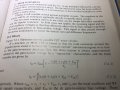
Please read pencil highlighted paragraph

Why should the 2 signals add?

Thanks
 

Attachments

Last edited:

WBahn

Joined Mar 31, 2012
29,976
I'm assuming that the Vs in the equation is the total gate-source voltage across the FET, what is more commonly referred to as Vgs?

If so, then as the paragraph describes, you can change Vgs either by changing the voltage on the gate or by changing the voltage on the source of the transistor.

I don't know where they define the voltages on the right side of the equation, but they may have a minus sign error in the two related to the source since as those signals go down (less positive or more negative) the Vgs increases while it the opposite for signals at the gate. But since these circuits are usually working with AC signals, that is often (sadly) overlooked.
 

Thread Starter

Zeeus

Joined Apr 17, 2019
616
If so, then as the paragraph describes, you can change Vgs either by changing the voltage on the gate or by changing the voltage on the source of the transistor.

I don't know where they define the voltages on the right side of the equation, but they may have a minus sign error in the two related to the source since as those signals go down (less positive or more negative) the Vgs increases while it the opposite for signals at the gate. But since these circuits are usually working with AC signals, that is often (sadly) overlooked.
Can you explain more please? don't understand
and dc Voltage on the gate is 0
Read the next paragraph and the image

Btw, it's the book you said you do not like
https://forum.allaboutcircuits.com/threads/wes-hayward-book.79505/
 

WBahn

Joined Mar 31, 2012
29,976
Can you explain more please? don't understand
and dc Voltage on the gate is 0
Read the next paragraph and the image

Btw, it's the book you said you do not like
https://forum.allaboutcircuits.com/threads/wes-hayward-book.79505/
Yes, DC voltage on the gate is zero, but the DC voltage on the source is not. Remember, this is a basic junction FET and so the current flow is max with Vgs = 0 (if Vgs becomes forward biased, current will flow through the gate junction and mostly likely damage the device). As you decreage Vgs (by taking it negative), the current in the FET will decrease until it is pinched off.

I did look at the next paragraph and the diagram (though I missed that there they indicate that Vs is purely the source voltage, not Vgs). But they don't define completely what the signal voltages are -- meaning exactly where they measured and what their polarity is -- but rather an incomplete qualitative description.

I'm not saying that I don't like the book -- I really don't know yet. Just that I bought it looking for a specific kind of treatment and it didn't provide it. If I ever get the chance to delve into this stuff more fully, I may well find it to be very useful once I am in a position to view it from the right perspective (or I could end up really not liking it).
 

Thread Starter

Zeeus

Joined Apr 17, 2019
616
Yes, DC voltage on the gate is zero, but the DC voltage on the source is not. Remember, this is a basic junction FET and so the current flow is max with Vgs = 0 (if Vgs becomes forward biased, current will flow through the gate junction and mostly likely damage the device). As you decreage Vgs (by taking it negative), the current in the FET will decrease until it is pinched off.

I did look at the next paragraph and the diagram (though I missed that there they indicate that Vs is purely the source voltage, not Vgs). But they don't define completely what the signal voltages are -- meaning exactly where they measured and what their polarity is -- but rather an incomplete qualitative description.
Please look at this (the online copy is blurry)
In the first image : can read from FET MIXERS but no need to read : 2nd image is important

In 2nd image and 2nd figure, it is easy for me to see that the 2 voltages (LO and RF) should add but not clear for the 1st figure in 2nd image

Maybe need concentrate
 

Attachments

MrAl

Joined Jun 17, 2014
11,389
Here is the first image in this thread cleaned up a little and made a smaller image size. No need to post huge drawings that are very simple.
 

Attachments

Thread Starter

Zeeus

Joined Apr 17, 2019
616
Here is the first image in this thread cleaned up a little and made a smaller image size. No need to post huge drawings that are very simple.
Correct : it went from Mb to that..What did you use to reduce size?
 

MrAl

Joined Jun 17, 2014
11,389
Correct : it went from Mb to that..What did you use to reduce size?
Hi,

I write my own software so i did a complete drawing program with image enhancements and that includes resizing, gamma correction, and stuff like that. But you can use many different programs even MS Paint that comes with Windows. Just look for the resize function. You can also lower the .jpg quality which works just fine with many types of pictures and that reduces the file size also (not sure if you can do that in MS Paint though).
 
Top