Facebook
 Google
 GitHub
 Linkedin
I'm working to learn how to build my own motor controller for what I envision to be an open source treadmill walking desk.
After playing with a number of arduino circuits and applications, I felt ready to move up in horsepower to treadmill-sized PMDC motor controllers, but found there's not yet much available that I could find by way of tutorials and helpful information for designing circuits at this amperage and voltage.
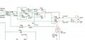
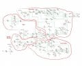
So I decided to study the motor controller on a used Proform treadmill that I inherited. It uses an MC-60 motor controller. On this forum, I found two relevant mc-60 schematics, one from Tom Rollins ("trolley1"), and the other from "SgtWookie".
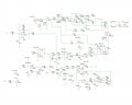
Tom Rollins commented with regard to his schematic that it might be missing some resistors, so I thought I'd engage my own learning with his schematic in the background to see if I could reproduce his schematic on Eagle CAD, which I also wanted to learn, by following his reverse-engineering process on my own PCB. I did that, and filled in names and values to devices for which I also downloaded data sheets. I found what I believe were a couple of mis-labeled devices, and a missing trace. I've attached my hopefully improved schematic here, and I blogged about the schematic and my process here.
These are two circuit-level changes from the Rollins' schematic (also attached) to mine. I've more than triple-checked them. I think I've got them correctly.
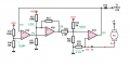
1) In the attached mc-60v4 schematic (mine) there's a start-up sub-circuit, I believe, centered on U2_A (under the speed control pot) connected through R20 to leg L (Low)(this is only faintly labeled on my schematic, I see). On Tom Rollins' schematic, he shows that to be connected to leg W (Wiper).
2) Between R7 near U2_D (below the LED SCR Trigger) and R9, the trace on my schematic including R10 does not show on Rollins' schematic.
At any rate, now I'm to the point of trying to better understand design elements of the circuit. I have a load of amateur-level questions, but I'll start with just three.
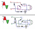
1) I understand how a full bridge rectifier converts AC to DC. The conversion here, as I understand will be pulsed to A+ anywhere from 0-120VDC. I understand how SCRs work. That given, how does 120VDC get stepped down to a steady 12VDC for the rest of the circuit? I see the circuit returns from the rectifier through D5, R14, between D4 and D% and through R9 (5KOhms). This probably is simple, but I've not figured it out for myself yet. Is the zenar diode, D10 key, I wonder?
2) What does D12 do in the rectifier that's helpful? Why is it there?
3) What do D4 and D3 do, and why are they connected to the AC input?
Understanding this would be for me a great start.
If anyone wants a copy of the Eagle CAD file or datasheets, let me know. Thanks in advance.
After playing with a number of arduino circuits and applications, I felt ready to move up in horsepower to treadmill-sized PMDC motor controllers, but found there's not yet much available that I could find by way of tutorials and helpful information for designing circuits at this amperage and voltage.
So I decided to study the motor controller on a used Proform treadmill that I inherited. It uses an MC-60 motor controller. On this forum, I found two relevant mc-60 schematics, one from Tom Rollins ("trolley1"), and the other from "SgtWookie".
Tom Rollins commented with regard to his schematic that it might be missing some resistors, so I thought I'd engage my own learning with his schematic in the background to see if I could reproduce his schematic on Eagle CAD, which I also wanted to learn, by following his reverse-engineering process on my own PCB. I did that, and filled in names and values to devices for which I also downloaded data sheets. I found what I believe were a couple of mis-labeled devices, and a missing trace. I've attached my hopefully improved schematic here, and I blogged about the schematic and my process here.
These are two circuit-level changes from the Rollins' schematic (also attached) to mine. I've more than triple-checked them. I think I've got them correctly.
1) In the attached mc-60v4 schematic (mine) there's a start-up sub-circuit, I believe, centered on U2_A (under the speed control pot) connected through R20 to leg L (Low)(this is only faintly labeled on my schematic, I see). On Tom Rollins' schematic, he shows that to be connected to leg W (Wiper).
2) Between R7 near U2_D (below the LED SCR Trigger) and R9, the trace on my schematic including R10 does not show on Rollins' schematic.
At any rate, now I'm to the point of trying to better understand design elements of the circuit. I have a load of amateur-level questions, but I'll start with just three.
1) I understand how a full bridge rectifier converts AC to DC. The conversion here, as I understand will be pulsed to A+ anywhere from 0-120VDC. I understand how SCRs work. That given, how does 120VDC get stepped down to a steady 12VDC for the rest of the circuit? I see the circuit returns from the rectifier through D5, R14, between D4 and D% and through R9 (5KOhms). This probably is simple, but I've not figured it out for myself yet. Is the zenar diode, D10 key, I wonder?
2) What does D12 do in the rectifier that's helpful? Why is it there?
3) What do D4 and D3 do, and why are they connected to the AC input?
Understanding this would be for me a great start.
If anyone wants a copy of the Eagle CAD file or datasheets, let me know. Thanks in advance.
Attachments
-
 274.7 KB Views: 2,111
 -
 118.2 KB Views: 1,934
 -
386.5 KB Views: 1,625