Understanding the cessna 152 electrical system

Thread Starter

Sierralima152

Joined Apr 6, 2025
4
Good day to you!

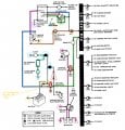
Today, I was hoping to stimulate your brain and your feel good hormones by posting this question about the good ol’ cessna 152 electrical system and asking you if you could help me ‘’unpretzel’’ my brain around it.

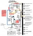
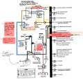
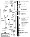
For the good cause, I added a textbook screenshot of the cessna 152 electrical system circuit from the aircraft manual AND a customized version of the same screenshot in case I don’t know what you’re referring to (so you can refer to it by (red triangle, blue line, cyan square, etc.).

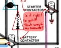
P.S. I know a couple of basic things, but I’m looking to deepen my knowledge. For your personal information I know how most of the things that aren’t highlighted work (except. The Alternator control unit) I know their purpose. E.g. I know that if I lose my battery my engine will keep going thanks to the magnetos. I know the alternator belt spins when the engine is running, but it doesn’t generate electricity unless I turn the alternator switch ON. I don’t understand how the alternator control unit works, which line does what I don’t understand which ground goes to the ground which one goes to the airframe. So basically I don’t understand anything else other than what I need to stay safe up there. I would like to be able to explain the diagram to my fellow student pilot brothers and sisters. I don’t know what the legend mean either (e.g. a diode, a resistor, etc.) If you can help me understand this diagram it would mean the world to me and my friends at the school!

A great day to you!

Respectfully,

me :)
 

Attachments

Externet

Joined Nov 29, 2005
2,627
Welcome, SL.
It would be convenient if your students get a clear version from a qualified teacher that knows electrical circuits instead of versions from a forum.
Looking at the circuitry shows being very simple but I will not take the place of a teacher for this subject.
Your students want to learn flying and not electrical circuits, schematics and components, even when it would not harm a bit understanding them.
 

Thread Starter

Sierralima152

Joined Apr 6, 2025
4
Hi!
Sorry for the confusion, I’m not a teacher/instructor. I’m a student pilot and I asked multiples young instructors at my school if they could explain it to me and they did. But unfortunately they don’t go any deeper than (MASTER ON = BATTERY ON = DISCHARGE = SYSTEM ON FOR 30 MIN BEFORE NO MORE BATTERY. So we need —> ALTERNATOR SWITCH ON = ALTERNATOR ON (thanks to the Engine and the Magnetos) = SYSTEM ON + BATTERY RECHARGING (Yay!!)

I would really like to understand the direction of the current, how it flows from one part to the other. (I don’t know if it goes both ways, one way or both in some case?), I would like to know how the alternator control unit thinks and it might be a stupid question but why are there so much grounds everywhere on the diagram? I don’t know what a diode, a resistor and what the 3 lines connected to the alternator do. No one seems to know that at my school.

On one hand I have to agree that when flying the plane it’s unnecessary to know more than that. On the other hand I think it’s weird that it’s the only system out of all the other systems that we don’t go deeper into… Some will say that we’re not electricians blablablah! … yet we’re not mechanics and here we are learning every single parts of metal that touches the engine. I think the electrical system is just as interesting and that we should know how the current flows from one part to the other just like we know how the hot air/cold air flows in and around the exhaust manifold/how the fuel flows from the carburetor to the cylinders etc.

So please, if you’re willing to help me it would be of immense help for me and some of my peers who are possibly as curious as me, just not as motivated to go seek outside help.

I thank you for your answer and I look forward to hearing from you again!!

have a good rest of your day!!

SL
 

WBahn

Joined Mar 31, 2012
32,732
The reason for all of the "ground" symbols is just to avoid decluttering the diagram. The "ground" for the plane is simply the metal frame of the aircraft (just like the ground for virtually all automobiles). It is nothing more than a common electrical connection point for everything -- think of it as being one big wire. The term "ground" does not mean the physical ground that you walk on. A better term would be "chassis".

The alternator control unit simply adjusts the strength of the magnetic field inside the alternator in order to increase or decrease the power output in response to sensing the voltage at its output. Another name for the control unit is "voltage regulator".

The starter contactor and battery contactors are electromagnetic solenoid relays. The solenoids are powered by the positive power terminal connected to them. They are energized with the control terminal (the small one -- middle one in the diagram) is grounded. For the battery contactor, this is down via the master switch, for the starter contactor, it is done via the ignition switch. When the battery contactor is disengaged, the electromagnet discharges its stored energy into the diode that is connected across it. Without that diode, your electrical system would see a short voltage spike that could damage your avionics, particularly radios, if they aren't turned off at that time.
 

MisterBill2

Joined Jan 23, 2018
27,236
Really, that picto-graphic rendering of a cross between an actual circuit drawing and a "wiring diagram" will really be of much value in explaining what items the different systems consist of, sort of describing what the different things do. So really, it's main value is in showing how the various parts of the system are connected, so that students will have a basic understanding of what is related to what. What I see as missing is a lot of labeling about what the individual items are. I am aware of that "symbols key", which allows the drawing to be much smaller and easier to print. BUT it fails to provide an adequate understanding. What is missing is a whole lot of explanations.
 

Thread Starter

Sierralima152

Joined Apr 6, 2025
4
Hello everyone! Thank you for your informative replies!

Sorry for the delay, my CPL checkride is next week and I’m in a rush over a couple of things to study before it.

After looking at the information I got here, and a bit of research since yesterday I updated the diagram of the aircraft manual and put a few comments/question here and there. I would like to know what ya’ll think about this ?

I put my questions in red pen/red highlighter.
I most likely made wrong current flows around the master switch or other parts (e.g. alternator) if that’s the case please do point it out. It will be much appreciated.

Thank you for your feedback,

Wishing you a great day!

SL

P.S. I will come back today to see, then I’ll go down the same path (learn and do my research) and you’ll hear from me tomorrow.

IMGUR link for better image quality:
 

Attachments

WBahn

Joined Mar 31, 2012
32,732
The master switch is two switches. Each switch connects the top-corner on its side to the bottom-corner on its side. There is no connection across the top. When the switch is off, the connection is broken. So the BAT side connects the wire to the battery contactor to GND when ON and leaves it disconnected when OFF. The ALT switch connects power from the alternator output and/or the primary bus to the power input of the voltage regulator when ON, and removes it when OFF.

The Alternator Field Circuit Breaker is a self-resetting circuit breaker that temporarily removes power to the alternator in overload conditions. The ALT circuit breaker is the one in the cockpit that the pilot can use to isolate the alternator from the electrical system in the event of a failure so that operation can continue off the battery.
 

Thread Starter

Sierralima152

Joined Apr 6, 2025
4
The master switch is two switches. Each switch connects the top-corner on its side to the bottom-corner on its side. There is no connection across the top. When the switch is off, the connection is broken. So the BAT side connects the wire to the battery contactor to GND when ON and leaves it disconnected when OFF. The ALT switch connects power from the alternator output and/or the primary bus to the power input of the voltage regulator when ON, and removes it when OFF.

The Alternator Field Circuit Breaker is a self-resetting circuit breaker that temporarily removes power to the alternator in overload conditions. The ALT circuit breaker is the one in the cockpit that the pilot can use to isolate the alternator from the electrical system in the event of a failure so that operation can continue off the battery.
Hi, I couldn’t wait until tomorrow to reply,

When you say the ALT switch connects power from the alternator output and/or the primary bus to the power input of the voltage regulator when ON. What do you mean by and/or ? Maybe it’s a personal misunderstanding of mine because of how I interpret on the diagram, it looks like one line separating in two so more like an AND to me. (The Alternator output looks like it is connected to the primary bus and and the ACU power in.)

BATTERY-ALTERNATOR
1.1 How does the battery stop sending current when the alternator takes over ? Does it do that or is it my personal misunderstanding ?
1.2 Where is the flow of current from the alternator to the battery ?
1.3 When the alternator generates current itake over the job of the battery, how does it work ? (Highlighter code: Yellow = alternator flow, black = battery flow)

LOW VOLTAGE WARNING LIGHT
2.0 Where does that go to ? The arrow ends with the following text: TO INST LTS CIRCUIT BREAKER
2.1 What does it mean when they say ‘’Low vol out’’ ? (I’m guessing it’s for ‘’low voltage light output’’)
BATTERY CONTACTORS (AKA ELECTROMAGNETIC SOLENOID RELAYS)
3.0 Did I get the flow right for the current from the different connections to it?

(The red ‘’S’’ stands for the switch that activates it. See screenshot)

Thank you for your help! We’re getting there! The diagram gets less cluttered with every question/answer.

SL.
 

Attachments

WBahn

Joined Mar 31, 2012
32,732
Your electrical system has two power sources (under normal conditions) -- a battery and an alternator. If the battery voltage is lower than the alternator voltage, power will be delivered to the battery to charge it, which will result in the battery voltage rising. At some point, the battery voltage will match the alternator output voltage and the battery will stop charging. From that point on, energy will effectively come from the alternator and the battery will be sitting there looking stupid. In reality, power will actually come from both, sometime more from the battery and sometimes more from the alternator, but any time the battery supplies some current, it's voltage will drop a bit, which will then cause the alternator's output to send current to the battery to charge it back up. The voltage regulator maintains the alternator's output at a voltage that will charge the battery but not overcharge it.

For most of the instrument lights, power goes from the bus to some kind of switch to the actual light and then to ground (in some cases, the switch and the light are swapped so that the switch is between the light and the ground instead of being between the light and the power bus -- the electrons don't care). The same is true for the low-voltage warning light. Power goes from the bus, through the instrument light fuse, to the actual light, and then to a switch and ground. But the switch (and ground connection) is within the alternator control unit.

For the two contactors, the high-current contacts are the ones one opposite sides of the cylinder. The one in the middle is one end of the electromagnet coil. The other end of coil is connected to one of the high current contacts (namely, the one that the power comes in from). So, in that diagram, the coil on the battery contactor is between the left two contacts and for the starter contactor it's between the right two. Many contactors have four posts, two high current contacts that are switched and two low-current contacts that go to the coil. Then there is an external strap that goes from one of the coil contacts to the proper high-current contact.
 

sparky 1

Joined Nov 3, 2018
1,218
The Cessna Diagram is broken down into sub circuits.
Each sub circuit has test points that indicate electrical specification are met

These diagnostic procedures have significance in explaining the how and why.
The best teaching will significantly reduce the risk of serious injury. These procedures make use of electrical testing.
It can start with writing and high lighting on a Cessna Diagram if that's how you learned then it is what it is,

An example: One person understands electrical theory and tests a wiring harness and says it is good and is confident and gets complacent.
Another person is taught the correct method for inspecting he finds an intermittent error and is keen about being thorough.
Is the emphasis on using the chassis ground symbol or using the right procedures the right parts and experience that makes airworthiness?

There are different styles and presentations. Are there some points that can be improved? maybe a part 2 could further clarify?

More classroom theory on the voltage reg/charge control (Skyhawk). Discuss this subcircuit then follow up with hands on multimeter testing.
A breadboard demo could be constructed showing both states: charging or when the charging is complete via reverse current relay.
 
Last edited:
Top